High-humidity smoke sampling sulfur dioxide separating device

A technology of sulfur dioxide and separation device, which is applied in the direction of sampling device and test sample preparation, etc., which can solve the problems of sulfur dioxide dissolution loss and achieve the effect of reducing dissolution loss and improving accuracy

Inactive Publication Date: 2009-10-21
张学平
View PDF1 Cites 7 Cited by
  • Summary
  • Abstract
  • Description
  • Claims
  • Application Information

AI Technical Summary

Problems solved by technology

[0007] In order to overcome the loss of sulfur dioxide dissolved by the existing dehumidification device, the present invention provides a new sampling treatment method - primary separation of water and gas in the flue, secondary separation of water and gas outside the flue under heating, and before entering the sensor components cool down again

Method used


Image

  • High-humidity smoke sampling sulfur dioxide separating device

Examples


Embodiment Construction

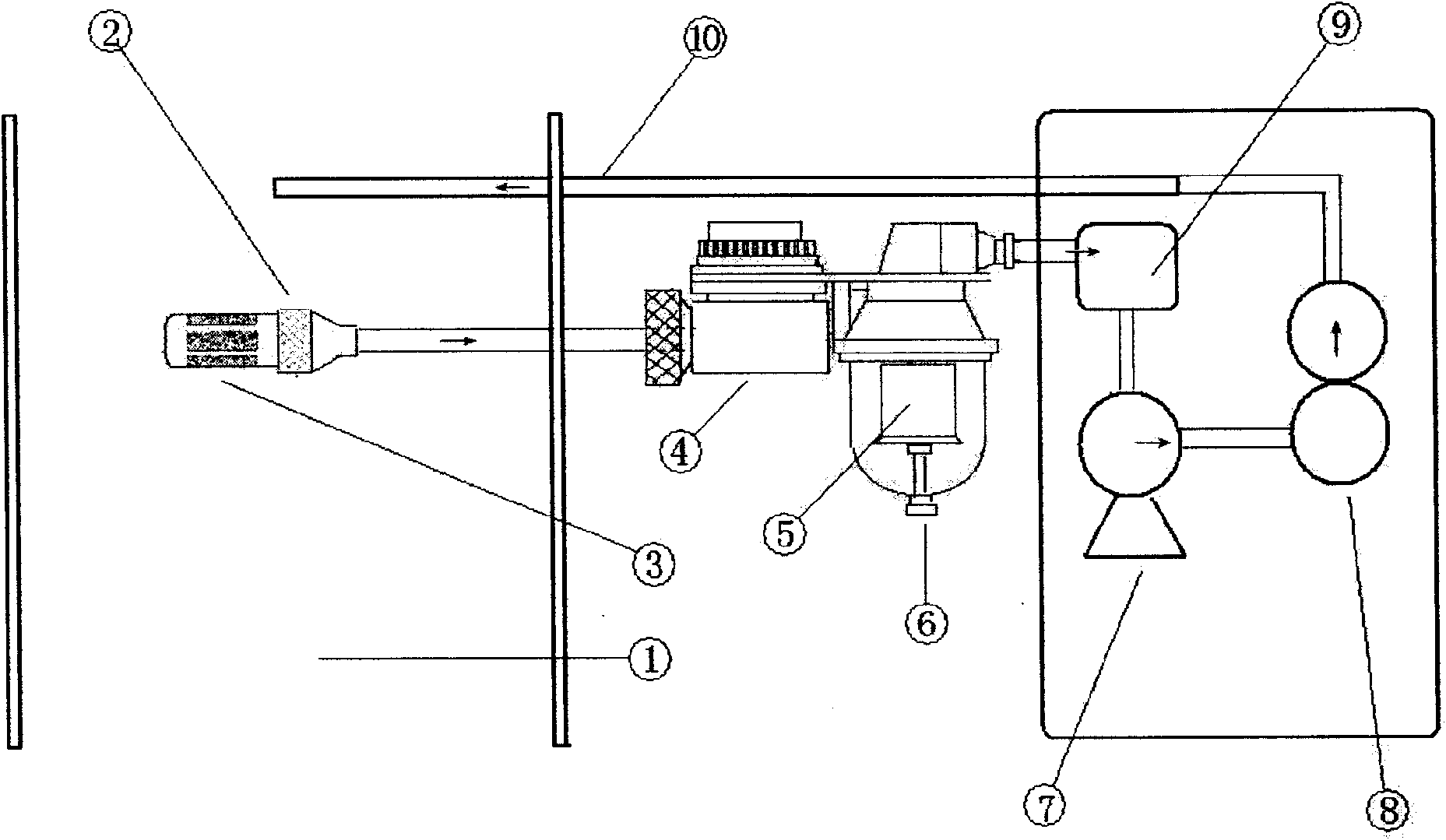
[0016] As shown in the accompanying drawings, insert the device of the present invention into the flue (1), start the suction pump (7), and the direction of the smoke in the pipeline is shown by the arrow in the figure. In the flue, the flue gas enters the sampling gun head (2) through the micropores of the hydrophobic and gas-permeable membrane (3), and the area of ​​the hydrophobic and gas-permeable membrane must be large enough to maintain the gas sampling flow. Most of the water mist in the flue is blocked from the gun. When the flue gas containing a certain amount of water vapor reaches the overheater (4) through the sampling gun rod, the temperature rises sharply, and the chemical reaction of sulfur dioxide dissolving in water takes place reversibly, that is, the sulfurous acid is decomposed into sulfur dioxide and water:

[0017] h 2 SO 3 =SO 2 +H 2 o

[0018] And the hydrophobic gas-permeable film (5) of the water-gas separator (6) following it has blocked most of...


PUM


Abstract

The invention relates to a high-humidity smoke sampling sulfur dioxide separating device which furthest reduces the solution loss of sulfur dioxide during on-line monitoring or site detection of high-humidity smoke. Water is separated from smoke under the condition of heating, and the water and the smoke are reduced in temperature before entering a sensor part. The device can selectively perform primary water and smoke separation in a flue.

Description

Technical field [0001] The invention relates to a fixed pollution source flue gas sampler, a flue gas analyzer, a flue gas pollutant rapid detector or a fixed pollution source flue gas continuous monitoring system in the field of environmental monitoring, in particular to a low-dissolution separation of sulfur dioxide in high-humidity flue gas device. Background technique [0002] At present, in the detection of sulfur dioxide emitted from flue gas in the industry, the problem of high moisture content in flue gas is often encountered. In particular, the widely used wet desulfurization technology makes the final exhausted flue gas present a high humidity. Sulfur dioxide is easily soluble in water to become sulfurous acid, and its chemical reaction formula is as follows: [0003] SO 2 +H 2 O=H 2 SO 3 [0004] In addition, in order to avoid high-humidity water vapor affecting or damaging sensor components, it is often necessary to pass through a condensation dehydration ...

Claims


Application Information

Patent Timeline
Patent Type & Authority Applications(China)
IPC IPC(8): G01N1/34G01N1/22
Inventor 张学平
Owner 张学平
Why Eureka
Try Eureka