Organic waste gas treatment device

A treatment device, a technology for organic waste gas, applied in the direction of combustion methods, lighting and heating equipment, tubular elements, etc., can solve the problem of insufficient heat recovery efficiency of regenerative combustion equipment, decreased ability of heat storage materials to absorb heat energy, and gas flow cycle To avoid problems such as property fluctuations, to achieve the effect of compact structure, stable oxidation area and stable gas flow

Active Publication Date: 2009-10-28
GUANGDONG JINMING MACHINERY
View PDF0 Cites 7 Cited by
  • Summary
  • Abstract
  • Description
  • Claims
  • Application Information

AI Technical Summary

Problems solved by technology

Regenerative combustion equipment uses the heat energy generated by the combustion of organic waste gas, so the energy consumption is low. However, during the operation of the equipment, the oxidation area often drifts to the heat storage area and causes shutdown; the switching valve is switched frequently, so that the switching valve The service life is short, and the operation failure rate is high; every time the gas flow direction is switched, the gas flow will fluctuate, that is, there is a shortcoming of periodic fluctuation of the gas flow during operation
In addition, in the later stage of the heat storage process, as the temperature of the heat storage material increases, the ability of the heat storage material to absorb heat energy decreases, and the temperature of the discharged airflow is higher, so the heat recovery efficiency of the heat storage combustion equipment is not high enough

Method used


Image

  • Organic waste gas treatment device
  • Organic waste gas treatment device

Examples


Embodiment 1

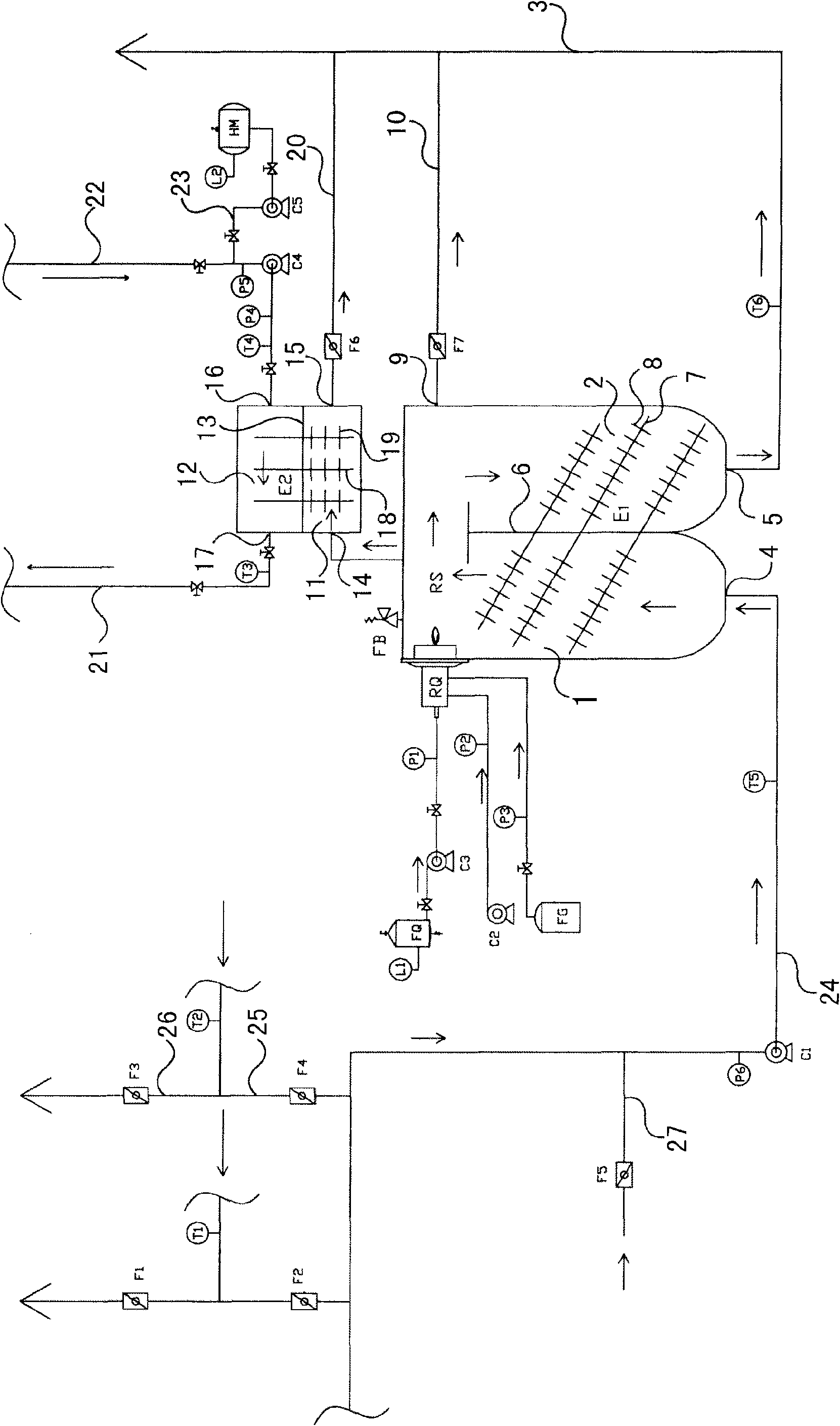
[0019] Such as figure 1 As shown, this organic waste gas treatment device includes an organic waste gas inlet pipe, a preheating chamber 1, a combustion chamber RS, a heat recovery chamber 2, an exhaust pipe 3, a heat pipe heat exchanger E1, and a heat transfer oil heat recovery device. Burner RQ is installed.

[0020] The preheating chamber 1, the combustion chamber RS ​​and the heat recovery chamber 2 are connected sequentially. The preheating chamber 1 is provided with a gas inlet 4, and the heat recovery chamber 2 is provided with a gas outlet 5. The organic waste gas enters the pipeline and is connected with the gas inlet 4. The gas pipeline 3 is connected with the gas outlet 5 . In this embodiment, the preheating chamber 1 and the heat recovery chamber 2 are arranged side by side, and a partition 6 is arranged between the preheating chamber 1 and the heat recovery chamber 2; the combustion chamber RS ​​is above the preheating chamber 1 and the heat recovery chamber 2, ...

Embodiment 2

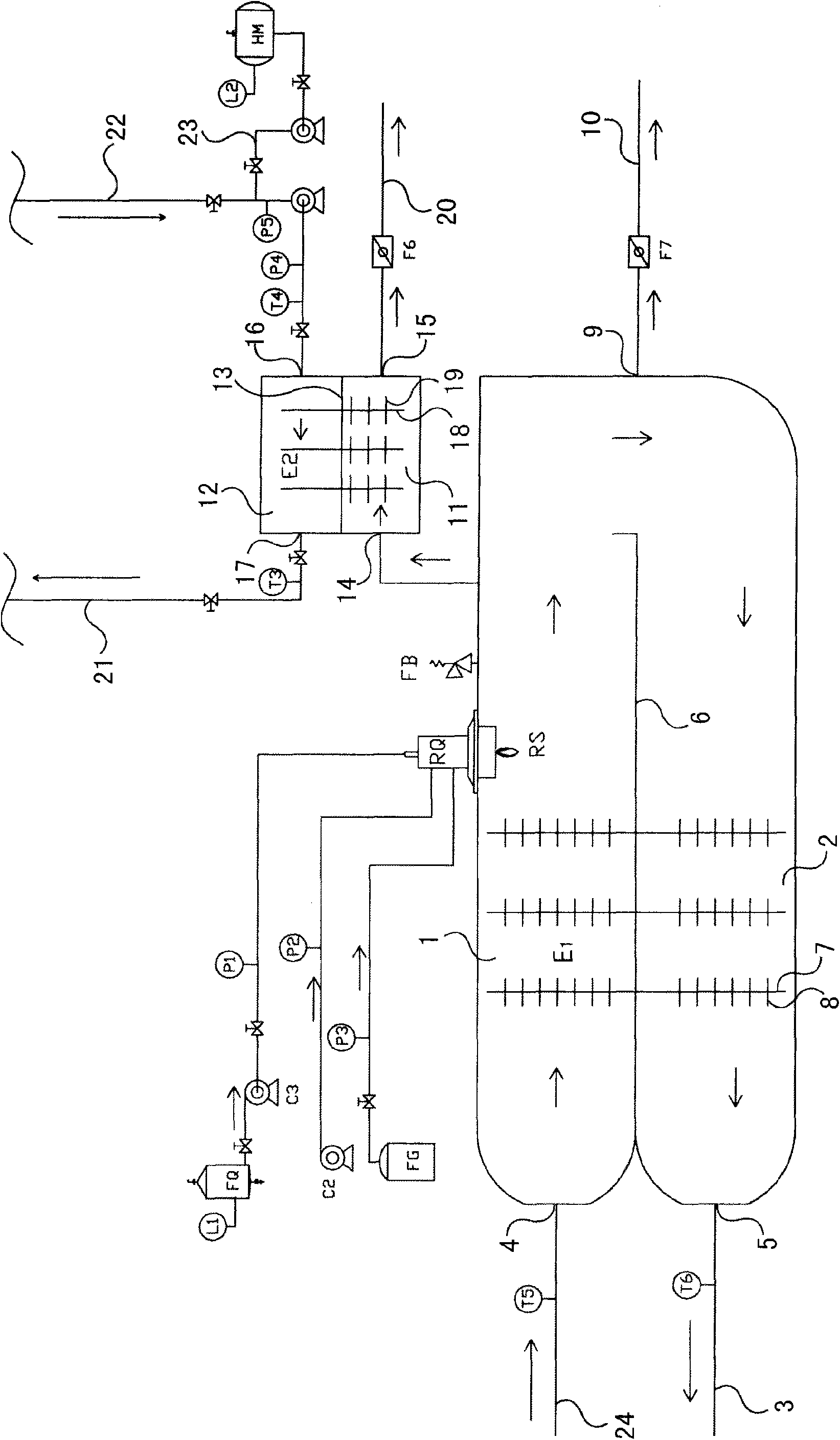
[0053] Such as figure 2 , in this organic waste gas treatment device, the preheating chamber 1 is arranged above the heat recovery chamber 2, and a partition 6 is arranged between the preheating chamber 1 and the heat recovery chamber 2, and the partition 6 is arranged along the horizontal direction, and the combustion chamber RS It is on the right side of the preheating chamber 1; the heat pipe 7 is installed on the partition 6, and the heat pipe 7 and the partition 6 are perpendicular to each other; in the heat recovery chamber 2, the heat pipe 7 is along the flow direction of the high-temperature gas generated after combustion (that is, from Right to left) are arranged step by step, correspondingly, in the preheating chamber 1, the heat pipes 7 are arranged step by step along the flow direction of the organic waste gas (that is, from left to right). The rest of the structure and working principle of the organic waste gas treatment device are the same as those in Embodiment...


PUM


Abstract

An organic waste gas treatment device is characterized by comprising a preheating chamber, a combustion chamber, a heat recycling chamber and a heat pipe exchanger. The preheating chamber, the combustion chamber and the heat recycling chamber are communicated in turn. An air inlet is installed on the preheating chamber, and an air outlet is installed on the heat recycling chamber. The heat pipe exchanger comprises at least one heat pipe. The two ends of the heat pipe are respectively positioned in the preheating chamber and the heat recycling chamber. The position of the end of the heat pipe, which is positioned in the heat recycling chamber, is lower than that of the heat pipe, which is positioned in the preheating chamber. A combustor is installed on the combustion chamber. The organic waste gas treatment device of the invention not only can fully dispose the organic waste gas, but also can recycle the heat energy generated in the combustion of the organic waste gas with high efficiency. The environment protection and the energy saving are integrated. The organic waste gas treatment device of the invention further has the advantages of low operation failure rate, stable and reliable operation, compact structure, and low operating cost. The application area of the invention is wide and can be used for all production techniques with waste gas discharge. The organic waste gas treatment device of the invention has more superiority for the production techniques of printing, coating, etc. with large waste gas amount and low content of organic waste gas.

Description

technical field [0001] The invention relates to equipment for treating waste gas, in particular to an organic waste gas treatment device. Background technique [0002] At present, combustion is generally used to treat organic waste gas, and organic waste gas is decomposed into harmless substances (such as carbon dioxide and water) through high-temperature oxidation. Traditional organic waste gas treatment devices include direct incineration equipment, catalytic combustion equipment and regenerative combustion equipment, etc. . [0003] Direct incineration equipment cannot use the heat energy generated by combustion to preheat organic waste gas, and the energy consumption is relatively high. [0004] Catalytic combustion equipment requires the use of catalysts, which has high operating costs, and is not applicable to all types of organic waste gas, and there are limitations in application. [0005] The common structure of regenerative combustion equipment is that it include...

Claims


Application Information

Patent Timeline
Patent Type & Authority Applications(China)
IPC IPC(8): F23G7/06F28D15/02F28F1/12
Inventor 黄炳潮熊鸿陈伟龙
Owner GUANGDONG JINMING MACHINERY
Why Eureka
Try Eureka