
Surface plasma coupling fluorescence detection apparatus

A surface plasmon and fluorescence detection technology, used in fluorescence/phosphorescence, material excitation analysis, spectrum investigation, etc., can solve the problems of affecting the accuracy of detection results, large beam divergence angle, low response speed, etc., to reduce background stray light The effect of interference, high detection accuracy and stable output power

Inactive Publication Date: 2009-10-28
XIAMEN UNIV
View PDF0 Cites 18 Cited by
  • Summary
  • Abstract
  • Description
  • Claims
  • Application Information

AI Technical Summary

Problems solved by technology

The weak point of this device is: 1, bulky, high power consumption
Although LED has the advantages of small size, low energy consumption, and cheap price, but because LED is an incoherent light source, its brightness is low, its monochromaticity is poor, its response speed is low, and its beam divergence angle is large, which can easily cause large background noise. , so a complex optical collimation system and focusing system are required
2. Complex structure and cumbersome operation
The whole device is prone to problems such as misalignment and defocusing, thus affecting the accuracy of the detection results
3. High manufacturing cost, which is not conducive to promotion and use
As a key component of the fluorescence detection system, the light source is often one of the most expensive consumables of the system, and it is impossible for a conventional laboratory to be fully equipped with a variety of expensive lasers
The structure of the double-table rotary table is complicated, and it cannot be purchased in ordinary photoelectric product manufacturing companies. It can only be customized in professional processing companies according to special specifications, which limits the promotion and application of SPCE methods in conventional laboratories.

Method used


Image

  • Surface plasma coupling fluorescence detection apparatus
  • Surface plasma coupling fluorescence detection apparatus
  • Surface plasma coupling fluorescence detection apparatus

Examples


Embodiment Construction

[0024] The present invention will be further described below in conjunction with the embodiments and accompanying drawings.

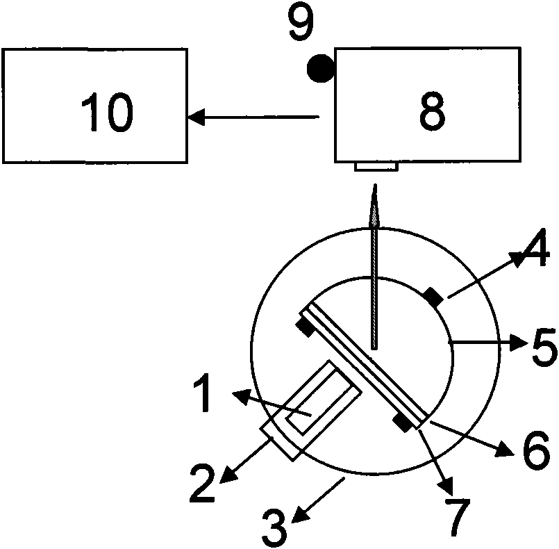
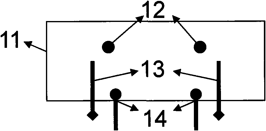
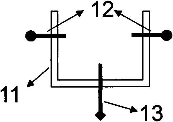
[0025] like figure 1 As shown, the present invention is provided with laser pointer 1 (light source), light source frame 2, rotating table 3, sample frame 4, coupling device (consisting of prism 5, nanoscale smooth metal film 6 and sample film 7), monochromator 8 , detector 9 and control processor 10. figure 2 and 3 The rest of the symbols in the figure indicate: 11 is the laser pointer casing, 12 is 2 fixing screws, 13 is 2 height adjustment screws, and 14 is 2 bracket screws.

[0026] see Figure 1~3 , the laser pointer 1 is installed on the light source frame 2, the light source frame 2 is set on the rotary table 3, the sample frame 4 is set on the rotary table 3, the coupling device is provided with a semi-circular rod prism 5, a nano-scale smooth metal film 6 and a sample film 7, the prism 5 is arranged on the sample holder 4, the nanoscale sm...


PUM

PropertyMeasurementUnit
Poweraaaaaaaaaa

Abstract

Surface plasma coupling fluorescence detection apparatus, relating to a fluorescence detection apparatus. The invention provides a surface plasma coupling fluorescence detection apparatus with small volume, simple structure, low cost, and high detection accuracy. The device is equipped with a light source, a light source rack, a rotating platform, a proof sample rack, a coupled device, a monochromator, a detector and a control processor. The light source is equipped on the light source rack, and the light source rack and the proof sample rack are equipped on the rotating platform. The coupled device is equipped on the proof sample rack. The monochromator is equipped on the side of the rotating platform, which receives fluorescence signal, and is connected with the detector. The detector is connected with the control processor. The device provided by the invention has the characteristics of compact conformation and miniaturization. Laser pen can be used as light source, with small volume, strong energy, and the laser pen combined with minitype monochromator can be used for realizing instrumentation miniaturization.

Description

technical field [0001] The invention relates to a fluorescence detection device, in particular to a surface plasmon coupled fluorescence detection device. Background technique [0002] Due to the advantages of high sensitivity and diverse methods, fluorescence technology is widely used in various analytical and characterization processes, especially in the field of biological sciences, including gene expression, drug diagnosis, and biohazard detection. Fluorophores on metal surfaces have unique fluorescent properties, which have the characteristics of enhanced fluorescence intensity, quantum yield and photostability. At present, many research directions are focused on the near-field interaction between metals and fluorophores, especially the research on Surface Plasmon Coupled Emission (SPCE). SPCE utilizes the near-field interaction between the excited state fluorophore and the nano-metal film within 200nm of the nano-metal surface. On the surface of a smooth metal film, ...

Claims


Application Information

Patent Timeline
IPC IPC(8): G01N21/64G01J3/28
Inventor 李耀群谢堂堂蔡伟鹏
Owner XIAMEN UNIV
Learn More