Aspheric fiber coupling lens
A fiber-optic coupling and aspheric surface technology, which is applied in the coupling of optical waveguides and other directions, can solve the problems of difficult cost reduction and increased manufacturing difficulty, and achieve the effects of improving applicability, positioning accuracy and low cost
- Summary
- Abstract
- Description
- Claims
- Application Information
AI Technical Summary
Problems solved by technology
Method used
Image

Examples
no. 1 example
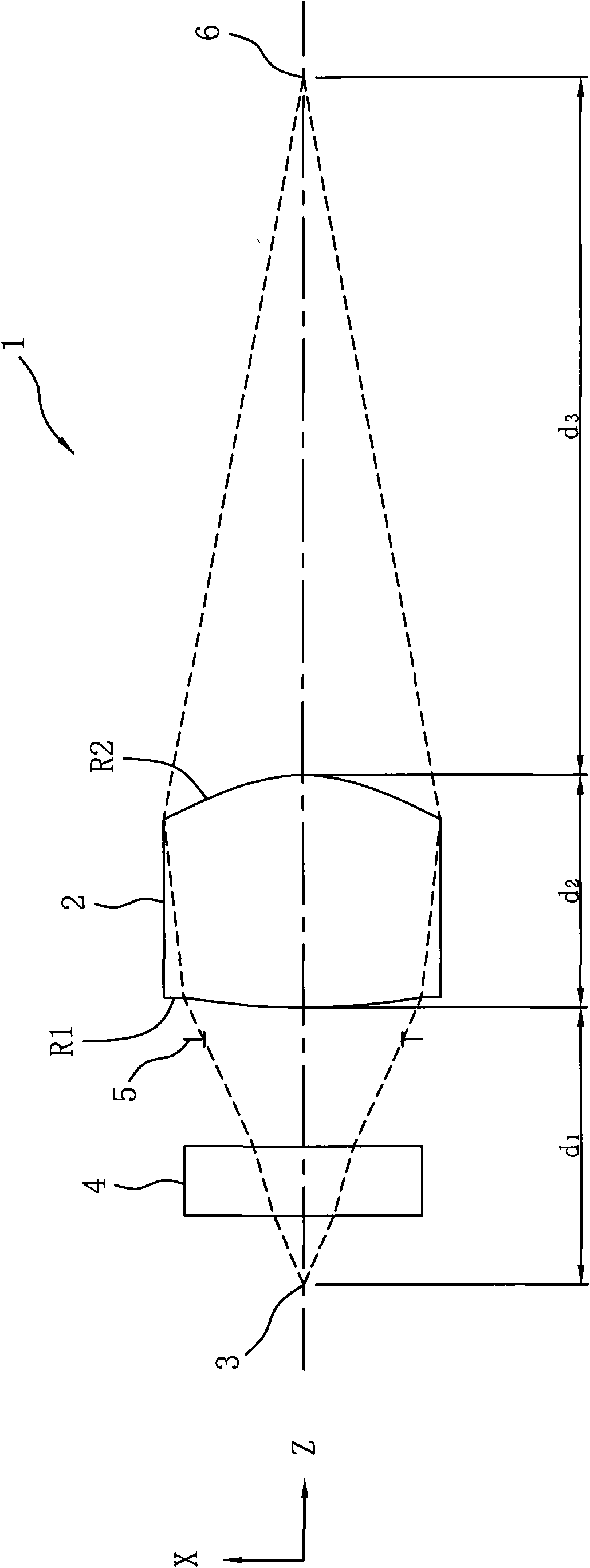
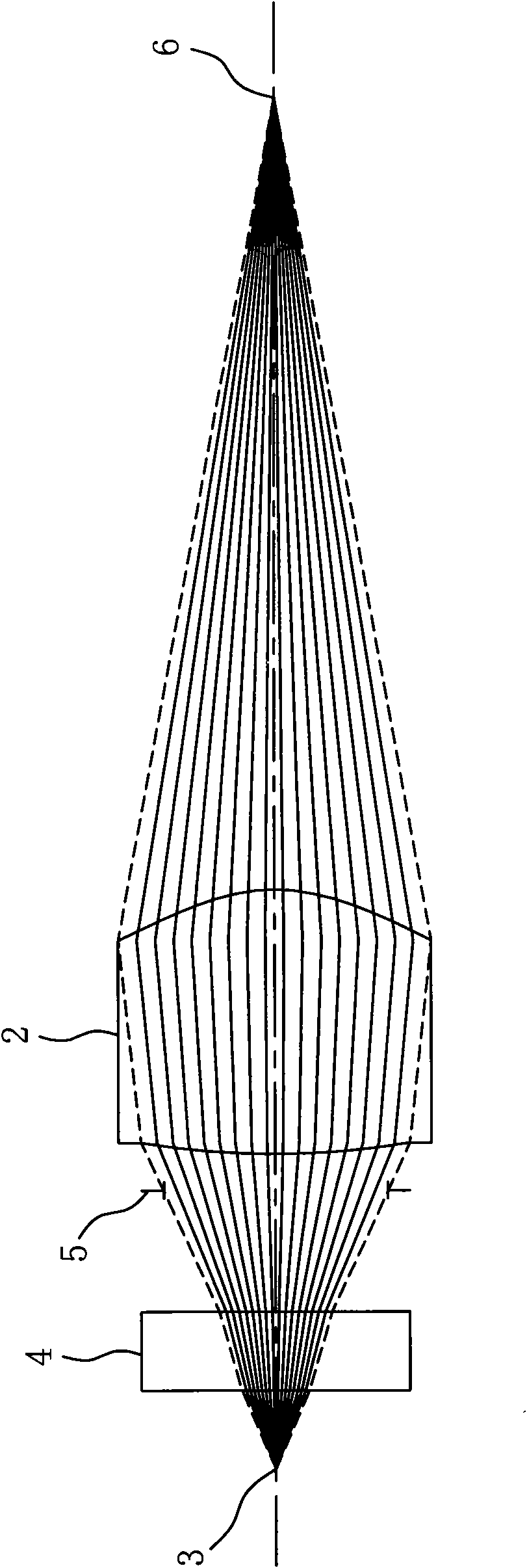
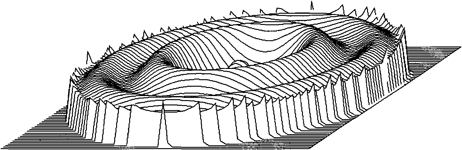
[0039] Please refer to figure 2 , 3 As shown, they are respectively a schematic structural diagram and a wave front aberration diagram of the first embodiment of the fiber coupling lens of the present invention; the fiber coupling lens 2 of this embodiment uses a glass material with a refractive index N d =1.58313, Abbe number v d =59.4, the first optical surface R1 and the second optical surface R2 are listed in the following table (1). The radius of curvature R (unit: mm) (the radius of curvature R) and the optical axis of the optical surface on the optical axis are listed. The thickness d2 of the fiber coupling lens 2 (unit: mm).
[0040] Table I)
[0041]
[0042]
[0043]In Table (1), f is the effective focal length, d2 is the thickness of the lens, nF is the refraction index, NAO is the number of apertures on the object side (number aperture on obj ective side), and NAI is the opening on the image side. The number of apertures (number aperture on image side), η is the c...
no. 2 example
[0049] The fiber coupling lens 2 of this embodiment uses a glass material with a refractive index N d =1.58313, Abbe number v d =59.4. The following table (2) lists the curvature radius R of the first optical surface R1 and the second optical surface R2 on the optical axis, the thickness d2 of the fiber coupling lens 2 on the optical axis, and the effective focal length. f. is the refraction value nF, the number of apertures on the object side NAO, the number of apertures on the image side NAI, and the coupling efficiency η.
[0050] Table II)
[0051]
[0052] From Table (2), it can be calculated:
[0053] d 2 f = 1.2023 ; R 1 - R 2 R 1 + R ...
no. 3 example
[0058] The fiber coupling lens 2 of this embodiment uses a glass material with a refractive index N d = 1.51424, Abbe number v d =63.7. The following table (3) lists the curvature radius R of the first optical surface R1 and the second optical surface R2 on the optical axis, the thickness d2 of the fiber coupling lens 2 on the optical axis, and the effective focal length. f. is the refraction value nF, the number of apertures on the object side NAO, the number of apertures on the image side NAI, and the coupling efficiency η.
[0059] Table (three)
[0060]
[0061] From Table (3), it can be calculated:
[0062] d 2 f = 0.8569 ; R 1 - R 2 R 1 + R ...
PUM
 Abstract
Description
Claims
Application Information
 - Generate Ideas
- Intellectual Property
- Life Sciences
- Materials
- Tech Scout
- Unparalleled Data Quality
- Higher Quality Content
- 60% Fewer Hallucinations
Browse by: Latest US Patents, China's latest patents, Technical Efficacy Thesaurus, Application Domain, Technology Topic, Popular Technical Reports.
© 2025 PatSnap. All rights reserved.Legal|Privacy policy|Modern Slavery Act Transparency Statement|Sitemap|About US| Contact US: help@patsnap.com