Finite element modeling method used for damage process of thermal barrier coating of turbine blade

A technology of turbine blade and thermal barrier coating, applied in the field of high-performance aero-engine thermal barrier coating system, can solve the problem of finite element simulation research, difficult to establish object model, Cumbersome operation and other problems, to achieve the effect of being conducive to R&D design and process optimization, easy to master and use, and to overcome incompatibility

Active Publication Date: 2009-10-28
XIANGTAN UNIV
View PDF0 Cites 32 Cited by
  • Summary
  • Abstract
  • Description
  • Claims
  • Application Information

AI Technical Summary

Problems solved by technology

However, the general-purpose finite element software program has very limited geometric modeling capabilities, and it is difficult to establish object models with complex geometric structures, and its workload is very large, and the operation is cumbersome. Therefore, it is urgent to develop related f

Method used


Image

  • Finite element modeling method used for damage process of thermal barrier coating of turbine blade
  • Finite element modeling method used for damage process of thermal barrier coating of turbine blade
  • Finite element modeling method used for damage process of thermal barrier coating of turbine blade

Examples


Embodiment 1

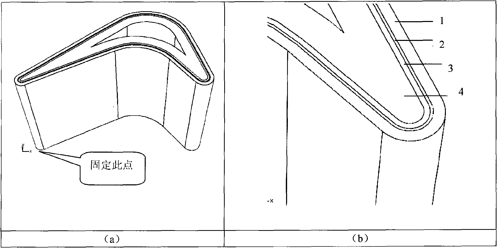
[0039] Select a single turbine blade thermal barrier coating system (without base) as the implementation object, such as figure 2 As shown in (a), establish its finite element analysis model, and carry out its finite element simulation under the action of thermal cycle.

[0040] For the sake of convenience and simplification, the present invention makes the following assumptions: 1) the materials of each layer of coating, substrate and base are uniform and all isotropic; 2) the thickness of each layer of coating is uniform; 3) the ideal elastoplastic model is adopted, and only High temperature creep of TBC layer; 4) This method only describes the finite element simulation of a single turbine blade TBC system.

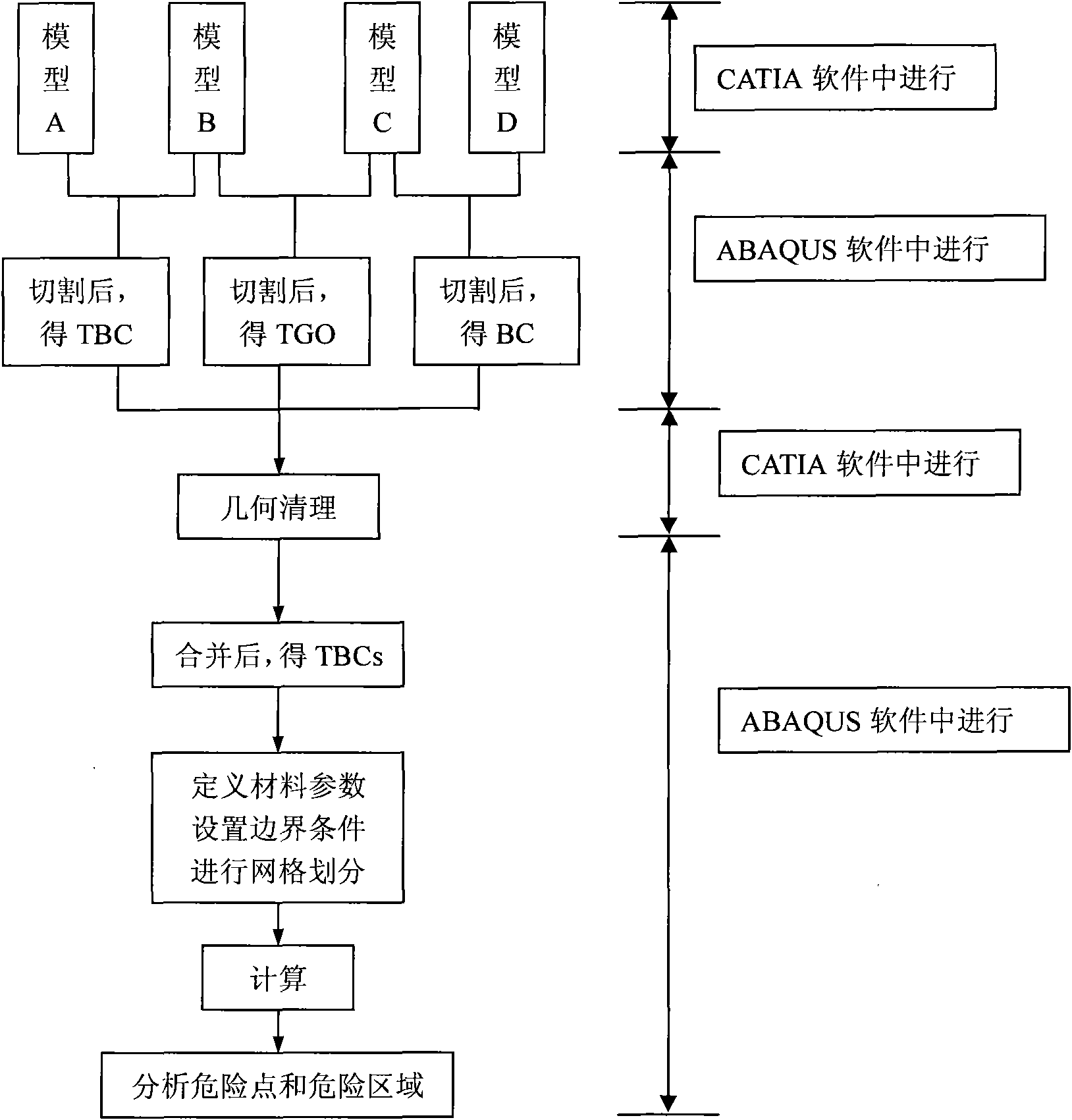
[0041] A finite element modeling method for the failure process of the turbine blade thermal barrier coating system, the flow chart of the method is as follows figure 1 shown, including the following steps:

[0042] (1) The establishment of the geometric model in the...

Embodiment 2

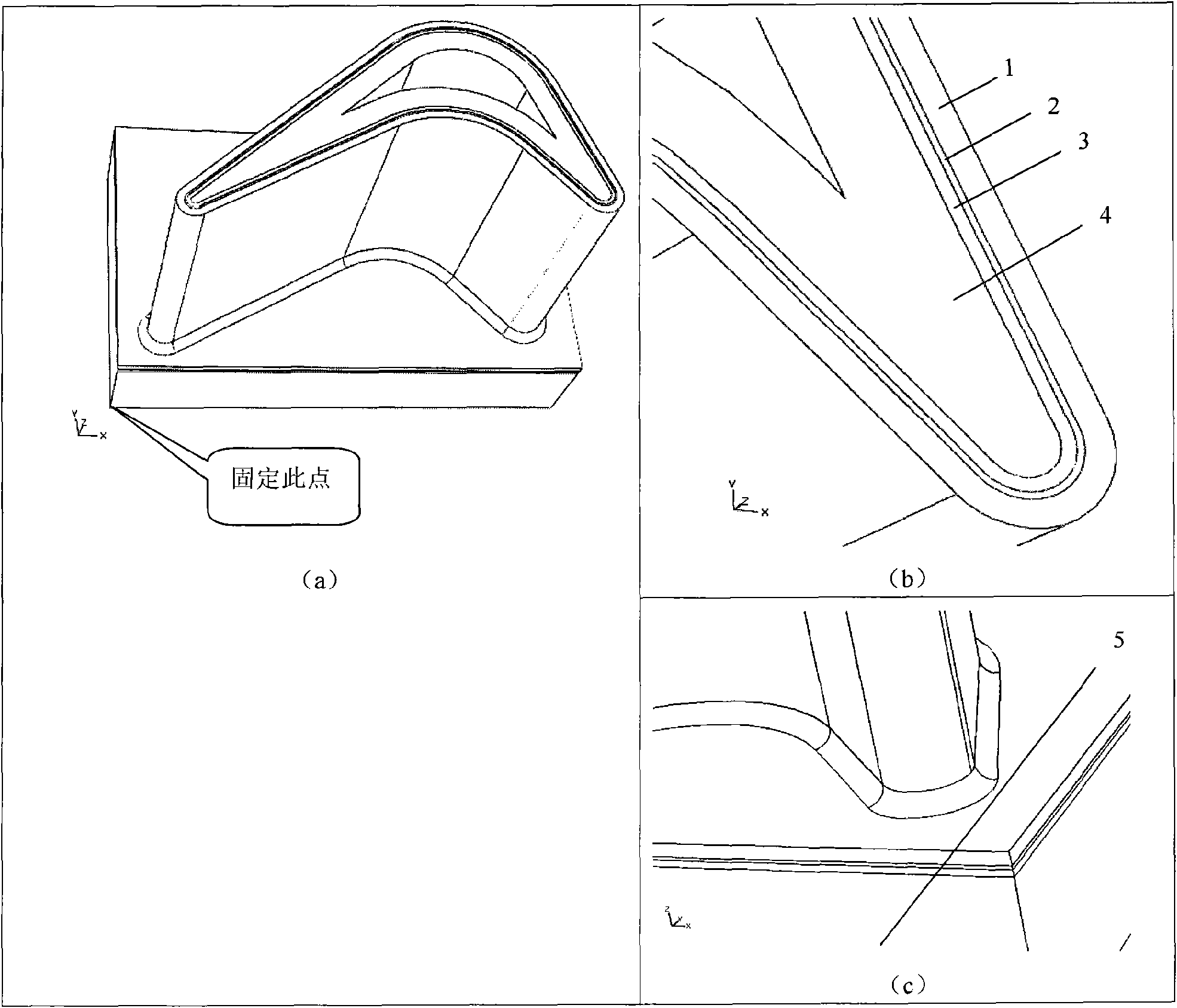
[0082] The turbine blade thermal barrier coating system with base is selected as the implementation object, such as image 3 As shown in (a), establish its finite element analysis model, and carry out its finite element simulation under the action of thermal cycle.

[0083] For the sake of convenience and simplification, the present invention makes the following assumptions: 1) the materials of each layer of coating, base and base are uniform and all isotropic; 2) the thickness of each layer of coating is uniform; 3) the base is simplified as a cuboid; elastoplastic model, and only consider the high temperature creep of the TBC layer; 5) This method only describes the finite element simulation of a single turbine blade thermal barrier coating system.

[0084] A finite element modeling method for the failure process of a turbine blade thermal barrier coating system, including the following steps:

[0085] (1) The establishment of the geometric model in the early stage

[0086...


PUM

PropertyMeasurementUnit
Stress valueaaaaaaaaaa

Abstract

The invention discloses a finite element modeling method used for damage processes of the thermal barrier coating of a turbine blade, belonging to the field of heat-insulation protection coating system technology of high-performance aero-engine. The method adopts a CATIA software and a finite element ABAQUS software. The method wholly models all coatings and the substrate in the CATIA software, carries out a secondary processing to geometrical models in the ABAQUS software, carries out geometrical cleaning to the model in the CATIA software, and carries out simulation, calculation and result analysis in the ABAQUS software. The method can effectively overcome the incompatibility of the CAD software such as CATIA and the like and the finite element software, considers both various properties of the heat barrier coating material and the geometrical shape of the substrate, can exactly simulate the relevant key physical quantity of the turbine blade heat barrier coating system in practical working environment, has clear concept and is convenient to be mastered and used by the technicians.

Description

technical field [0001] The invention belongs to the technical field of high-performance aero-engine thermal barrier coating systems, and in particular relates to a finite element modeling method for the destruction process of a turbine blade thermal barrier coating system. Background technique [0002] Thermal barrier coatings (thermal barrier coatings, referred to as TBCs) are based on the characteristics of ceramic materials such as high melting point, low thermal conductivity, low vapor pressure, low emissivity and high reflectivity. It is the surface of turbine blades) to reduce the working temperature of high-temperature components, protect them from high-temperature corrosion and high-temperature oxidation, greatly prolong the service life of high-temperature components, and enable high-temperature alloy components in modern aviation gas turbine engines to serve at temperatures higher than their melting points It becomes possible to work in the environment, thereby imp...

Claims


Application Information

Patent Timeline
IPC IPC(8): G06F17/50G06T17/40G06T19/00
Inventor 周益春刘奇星毛卫国蒋俊平
Owner XIANGTAN UNIV
Why Eureka
Try Eureka