

Solar power station
A solar cell and solar energy technology, applied in the field of solar power stations, can solve the problems of large size, inconvenient installation and maintenance, and easy damage to the power station.
- Summary
- Abstract
- Description
- Claims
- Application Information
AI Technical Summary
Problems solved by technology
Method used
Image

Examples
Embodiment Construction
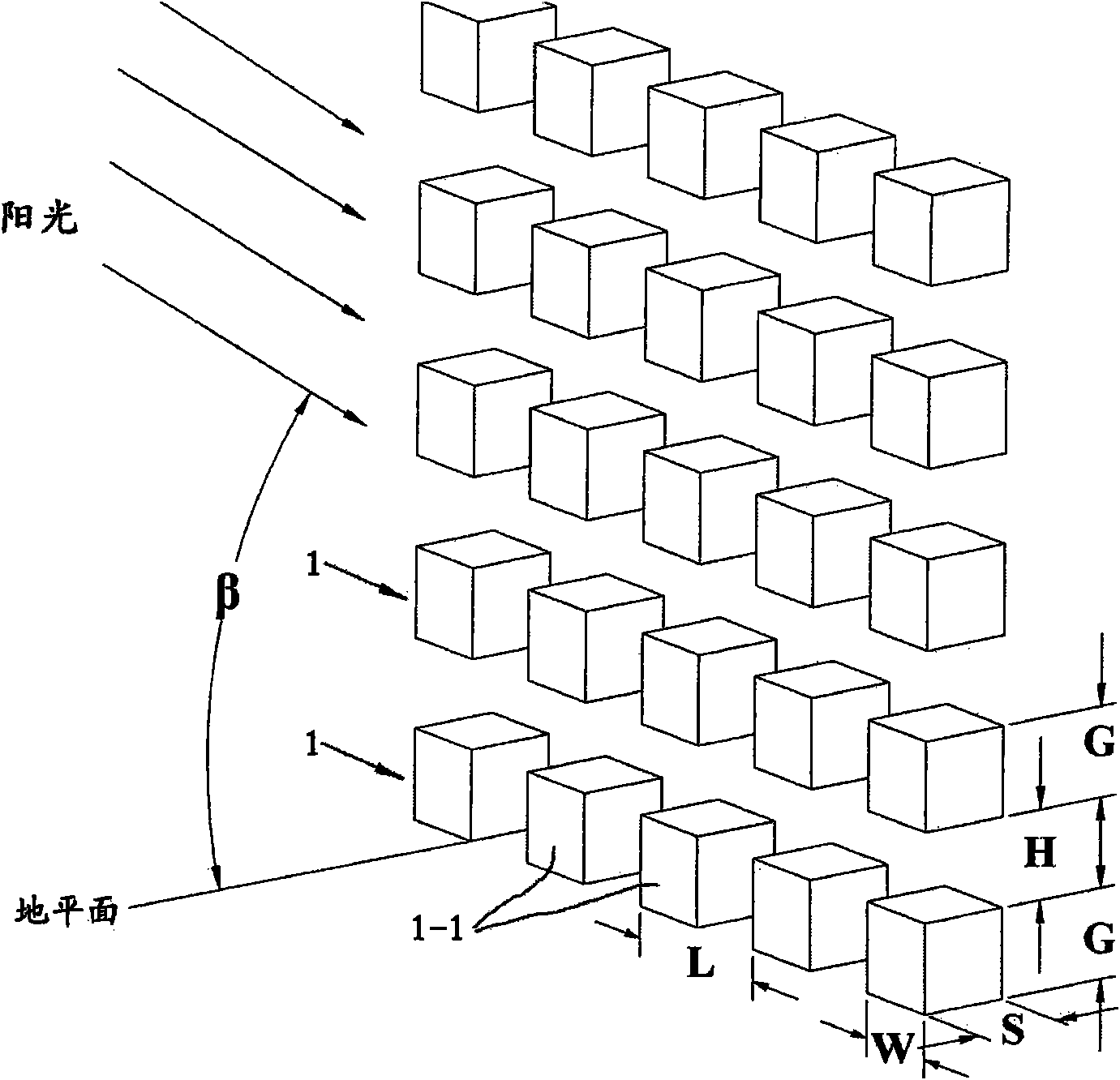
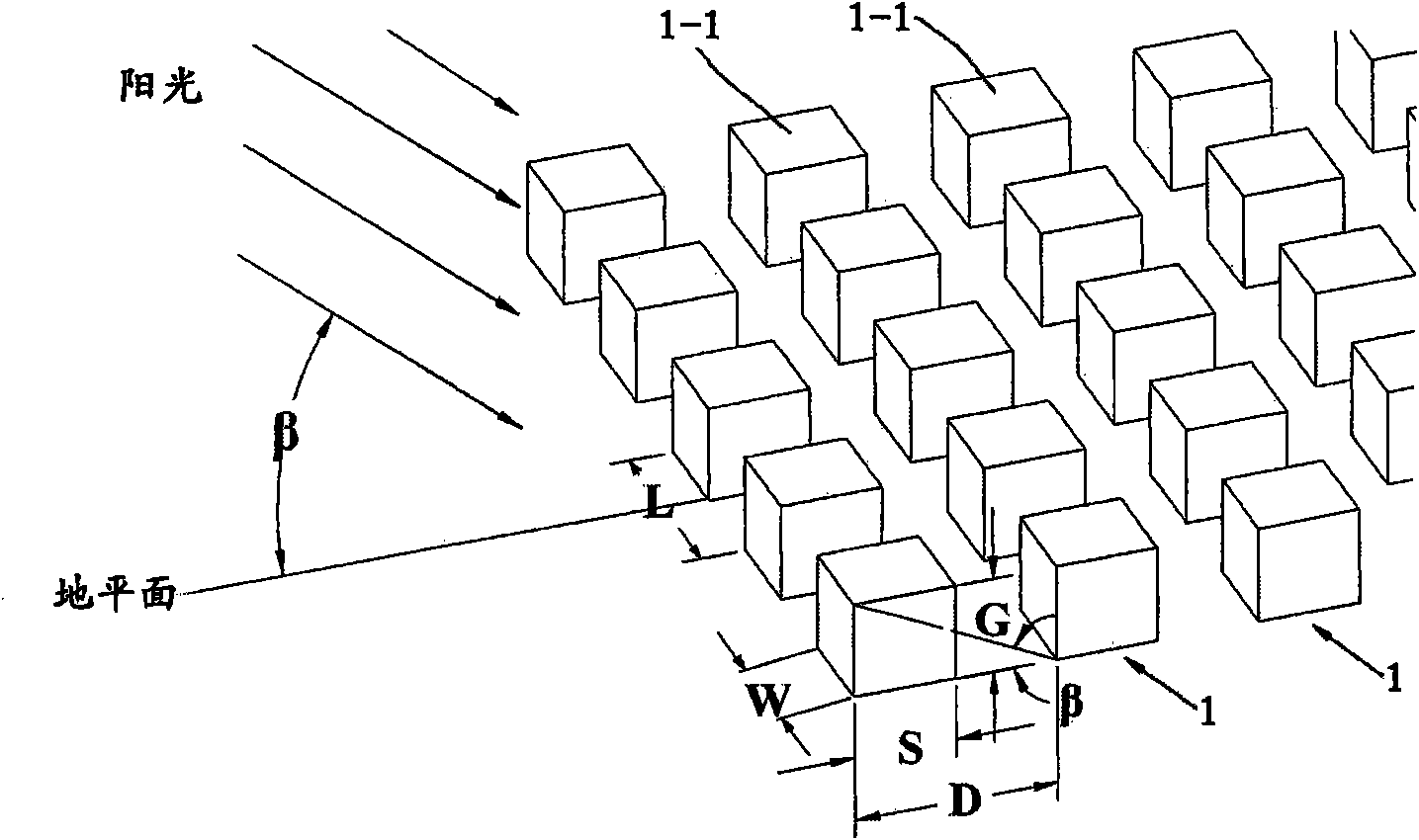
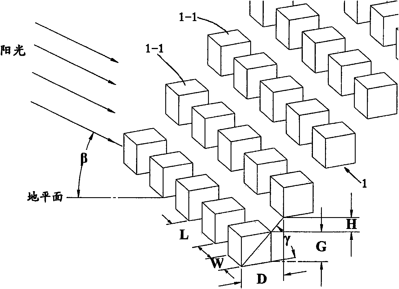
[0017] see Figure 1 to Figure 5 The solar power station shown includes several concentrating solar cell modules 1-1 that are electrically connected, and each of the concentrating solar cell modules 1-1 includes: a Fresnel lens or a convex lens, etc. Concentrating lens, solar cell semiconductor chip, horizontal rotation driving mechanism for driving concentrating solar cell unit module 1-1 to follow the horizontal movement of the sun, and pitch rotation for driving concentrating solar cell unit module 1-1 to follow the sun’s pitching movement The driving mechanism, the plurality of concentrating solar battery monomer modules 1-1 form a module array (1) arranged at a distance L from each other along the horizontal direction, and the L satisfies the relational expression: L=W / cosα, the formula Middle: W is the width of the concentrating solar cell unit module 1-1, and α is the azimuth angle of the sun determined by the latitude θ of the installation site of the power station. T...
PUM
 Abstract
Description
Claims
Application Information