Electronic ballast for fluorescent lamp

A technology for electronic ballasts and fluorescent lamps, applied in the direction of light sources, electric light sources, electrical components, etc., can solve problems such as unsatisfactory effects, rough lamp power control, and inoperable circuits, achieving better preheating effect and shortening the process. time, the effect of prolonging the service life

Inactive Publication Date: 2009-11-04
时宁立
View PDF4 Cites 5 Cited by
  • Summary
  • Abstract
  • Description
  • Claims
  • Application Information

AI Technical Summary

Problems solved by technology

More importantly, for the filament, the best working temperature is 900°C. At this time, the electron powder has a strong emission ability. If the preheating time of the filament is not enough or the preheating time is too long, the best effect cannot be achieved, and the market The electricity changes from 180v to 250v, and the voltage change will directly affect the preheating current output by the ballast. If the preheating time cannot be adjusted according to the external voltage change, the best preheating effect will not be achieved.
At present, most of the existing electronic ballasts use a typical voltage-fed half-bridge inverter circuit to preheat the fluorescent lamp filament. Most of them use thermistor preheating method, and some of them have chip control. Frequency conversion preheating method, but these two preheating methods have defects. If the thermistor is used for preheating, the preheating time cannot be controlled first, and the preheating time cannot be adjusted according to the change of the mains power. It has the best preheating, and secondly, the characteristics of the thermistor change with the change of room temperature, which is not stable enough; if the chip is used for frequency conversion preheating, since the chip is provided by foreign manufacturers, it basically does not provide this function, so the effect is not very good. ideal
[0005] At present, the dimmer switch also has a relatively high price, and there is a problem that the dimmer switch needs to be installed separately. Its internal core components are bidirectional thyristor and bidirectional trigger diode, and the bidirectional trigger diode is turned on after the voltage reaches 30v-50v. , so that even when the dimmer switch is in the brightest state, the circuit does not work for a short period of time. The phenomenon seen is: when the dimmer switch is adjusted to the maximum brightness, the brightness of the fluorescent lamp is weaker than that of the non-dimmable energy-saving lamp. It is a very regrettable problem that the dimming is changed at the expense of brightness.
Several patents of other dimming electronic rectifiers also mention the built-in dimming circuit module, basically through frequency conversion dimming, there are several shortcomings: 1. It must be used with a dedicated chip and a field effect tube , the circuit is complicated and the cost is high; 2. The control frequency of frequency conversion dimming is relatively accurate, but the corresponding lamp power control is very rough. For different lamp tubes of the same model and manufacturer, the same control frequency appears due to the different characteristics of each lamp tube Relatively large output power difference, sometimes up to 40% error; 3. When the frequency changes, the power of the output lamp will change suddenly, resulting in flickering phenomenon, which will affect the service life of the lamp tube

Method used


Image

  • Electronic ballast for fluorescent lamp
  • Electronic ballast for fluorescent lamp
  • Electronic ballast for fluorescent lamp

Examples


Embodiment Construction

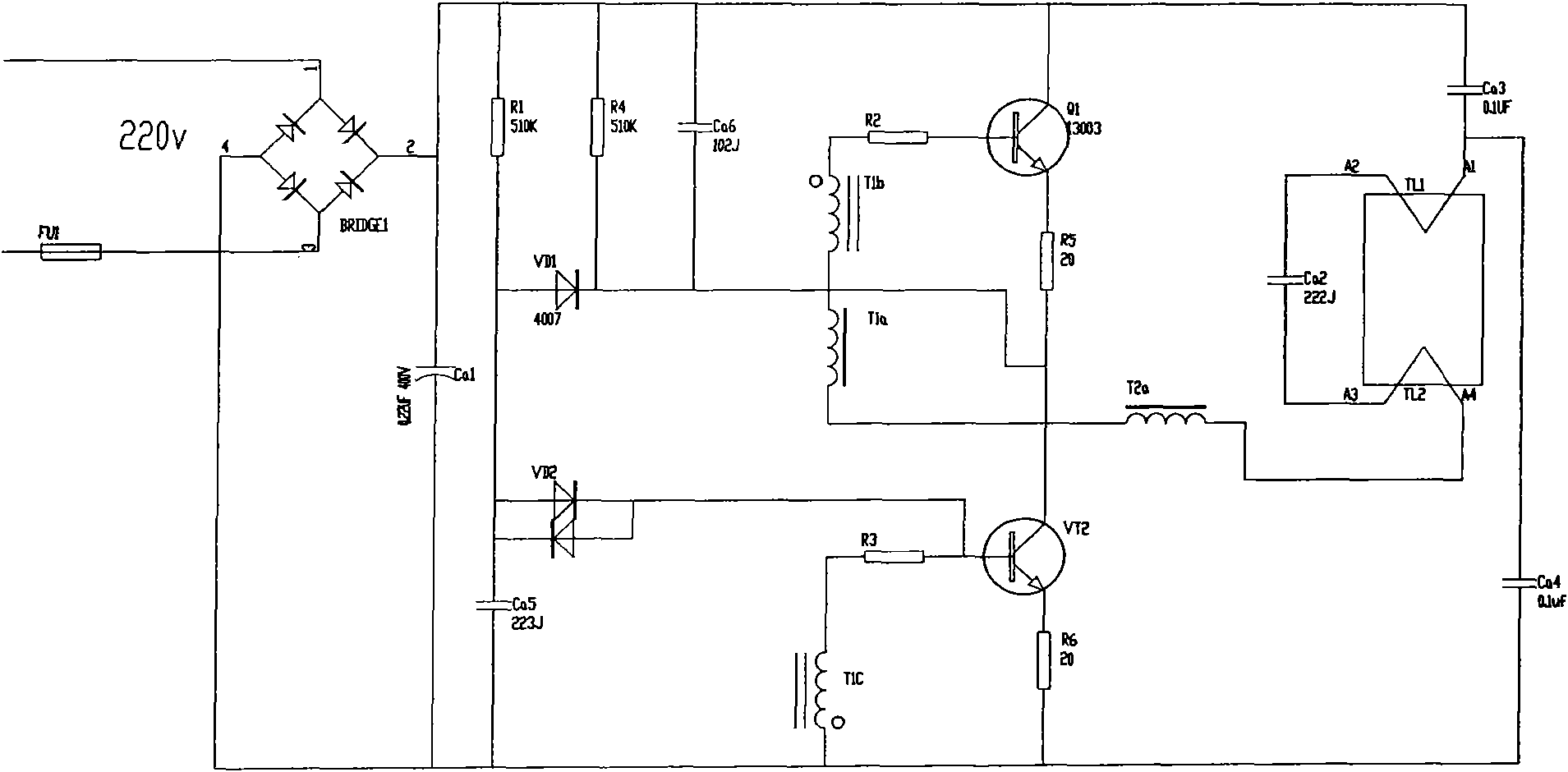
[0024] see figure 1 , is the circuit diagram of the existing typical basic half-bridge ballast. When the circuit is powered on, the resistance Ra flows through the 1 The current to the capacitance Ca 5 charging, when the capacitor Ca 5 The voltage across the two ends reaches the bidirectional trigger diode VD 2 When the trigger voltage (about 35V or so), VD 2 Avalanche breakdown, when the capacitor Ca 5 Through the switch tube VT 2 The base → emitter discharge, VT 2 is turned on due to the forward bias of the emitter junction, at VT 2 During conduction, the current path is: +VDC→Ca 3 → Tube Filament FL 1 →Ca 2 → Filament FL 2 → Ballast inductor La 1 →Ta 1 Primary coil Ta 1a →VT 2 collector → VT 2 The emitter → ground, the switch tube VT 2 The instantaneous change in collector current is Through the oscillating coil Ta 1a The two secondary windings Ta 1b and Ta 1c The corresponding induced electromotive force is generated, and the polarity of the induced el...


PUM


Abstract

The invention discloses an electronic ballast for a fluorescent lamp, which comprises a half-bridge inverter circuit module with an inductor, a singlechip control circuit module, and is also provided with a preheat circuit module and a built-in dimming circuit module, wherein the preheat circuit module is a bidirectional silicon-controlled circuit module controlled by a triode type opto-coupler, a control signal of the preheat circuit module is from the singlechip control circuit module, and a power supply is from the secondary side of the inductor; and the dimming circuit module is an unidirectional silicon-controlled dimming circuit module, a control signal of the dimming circuit module is from the singlechip control circuit module, a power supply of the dimming circuit module is from a 5V power supply of the singlechip control circuit module, and the dimming circuit is used for controlling a ground terminal of the basic half-bridge inverter circuit module. The electronic ballast can adjust the preheating of a fluorescent light tube correspondingly, prolong the service life of the fluorescent light tube, simultaneously shorten the conversion process time of the fluorescent lamp after the preheating is completed, ensure that damages to a light tube when the fluorescent lamp is turned on each time are reduced to minimum, accurately control dimming and has a simple structure.

Description

technical field [0001] The present invention relates to the technical field of electronic and electric light sources, in particular to an electronic ballast for fluorescent lamps. Background technique [0002] Fluorescent lamps are now the most important artificial light source and are widely used all over the world, especially in the field of industrial and commercial lighting. Since June 3, 2007, the State Council has issued the "Notice of the State Council on Printing and Distributing Comprehensive Work Plans for Energy Conservation and Emission Reduction" (Guo Fa [2007] No. 15), during the "Eleventh Five-Year Plan" period, the state supports high-efficiency lighting products through financial subsidies. Replace incandescent lamps and other low-efficiency lighting products in use, and accelerate the promotion and use of high-efficiency lighting products. However, the current fluorescent lamps still have certain problems. For the energy-saving lamps in fluorescent lamps, ...

Claims


Application Information

Patent Timeline
Patent Type & Authority Applications(China)
IPC IPC(8): H05B41/295H05B41/36H02M7/757
Inventor 时宁立
Owner 时宁立
Why Eureka
Try Eureka