Balun-free low-section plane two-arm groove helical array antenna

An array antenna and low-profile technology, which is applied in the field of balun-free low-profile planar two-arm slot helical array antenna, can solve the problem of increasing the total volume of the antenna, and achieve the effects of reduced size, low profile, and reduced distance

Inactive Publication Date: 2009-11-25
SHANGHAI UNIV
View PDF1 Cites 23 Cited by
  • Summary
  • Abstract
  • Description
  • Claims
  • Application Information

AI Technical Summary

Problems solved by technology

Literature (HISAMATSU NAKANO, KAZUO NOGAMI, SATOSHI ARAI, HIROAKI MIMAKI and JUNJI YAMAUCHI, "A Spiral Antenna Backed by a Conducting Plane Reflector", IEEE Trans. Antennas Propagat., vol. AP-34, pp.791-796, June 1986) Use a metal plate to make the

Method used


Image

  • Balun-free low-section plane two-arm groove helical array antenna
  • Balun-free low-section plane two-arm groove helical array antenna
  • Balun-free low-section plane two-arm groove helical array antenna

Examples


Embodiment Construction

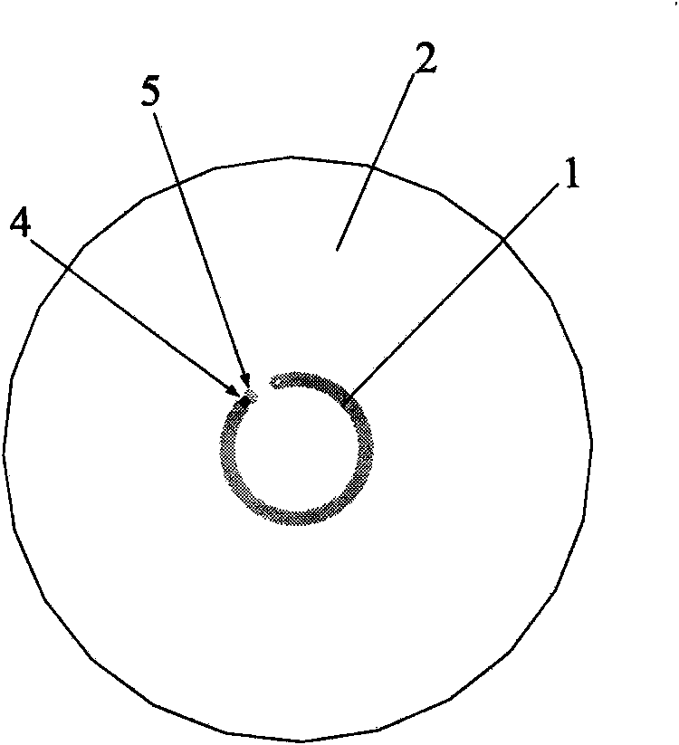
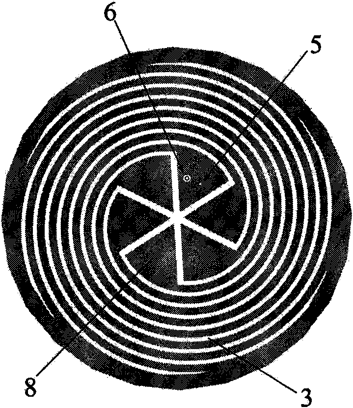
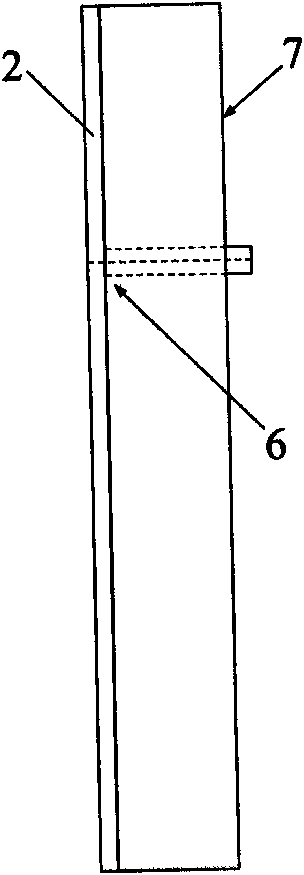
[0021] A preferred embodiment of the present invention is described in detail as follows in conjunction with the accompanying drawings: the structure of the antenna is as follows figure 1 , figure 2 with image 3 shown. This embodiment includes: an annular microstrip transmission line 1, a ceramic dielectric plate 2, a planar two-arm slot spiral array 3, an absorption resistor 4, a metallized via hole 5, a coaxial joint 6, a metal back cavity 7, and a metal ground plate 8. The annular microstrip transmission line 1 and the absorbing resistor 4 are located on the front of the ceramic dielectric board 2 , and the planar slot helical antenna 3 , the coaxial connector 6 and the metal back cavity 7 are all located on the back of the ceramic dielectric board 2 .

[0022] One end of the annular microstrip transmission line is connected to the coaxial connector 6 and the other end is connected to the snubber resistor 4 . The circumference of the annular microstrip line is a wavele...


PUM

PropertyMeasurementUnit
Thicknessaaaaaaaaaa

Abstract

The invention relates to a balun-free low-section plane two-arm groove helical array antenna, composed of an annular microstrip transmission line, a ceramic medium plate, a plane two-arm groove helical array, an absorption resistance, metalized via hole, a coaxial joint, a metal carinal cavity and a metal ground plate. The annular microstrip transmission line connecting the coaxial joint and the absorption resistance is on the front face of the ceramic medium plate; the plane two-arm groove helical array is etched on the metal ground plate of the ceramic medium plate; and the annular plane metal carinal cavity is on the back of the ceramic medium plate. Echo loss within 1.52 to 1.62 GHz is less than -10dB. The antenna has good gain and axial specific characteristic. The antenna needs no balun, has features of low section, miniaturization, simple structure and easy implement, and can be used as a terminal receiving antenna of a plurality of satellite navigation and positioning systems.

Description

technical field [0001] The invention relates to a balun-free low-profile planar two-arm slot spiral array antenna, which can be used as a terminal receiving antenna in various satellite navigation and positioning systems. Background technique [0002] Satellite navigation and positioning system is more and more widely used in people's life, and people have more and more researches on the receiving antenna of the user terminal of satellite navigation and positioning system. The planar helical antenna has ultra-wide frequency band, stable gain and low axial ratio, which makes it widely used in various military applications and commercial fields of ultra-wideband circularly polarized antennas. The satellite positioning system puts forward higher requirements on the stability of the phase center of the antenna, and requires the antenna to have a uniform and stable phase response. The planar helical antenna has the characteristics of high phase center stability. keen interest. ...

Claims


Application Information

Patent Timeline
IPC IPC(8): H01Q1/38H01Q13/00H01Q13/08H01Q21/00
Inventor 钟顺时陈敏华李丽娴
Owner SHANGHAI UNIV
Why Eureka
Try Eureka