
Device for fault diagnosis of electric brush slip ring and method for mechanism diagnosis and maintenance and design

A technology of brush slip ring and diagnostic device, which is applied in the direction of electromechanical devices, measuring devices, manufacturing motor generators, etc., to achieve the effect of reducing failure rate and preventing safety

Active Publication Date: 2009-11-25
北京唐智科技发展有限公司
View PDF0 Cites 38 Cited by
  • Summary
  • Abstract
  • Description
  • Claims
  • Application Information

AI Technical Summary

Problems solved by technology

[0013] Purpose of the present invention: to solve the problem of multi-generator brush slip ring faults such as wind power generators and rail transit equipment, and to propose a diagnostic device and mechanism diagnosis and maintenance design method for brush slip ring faults, including preventing or reducing brush slip ring faults. Advanced maintenance and improved design schemes for slip ring faults, and fault diagnosis devices and fault mechanism diagnosis methods for existing brush slip ring faults of equipment

Method used


Image

  • Device for fault diagnosis of electric brush slip ring and method for mechanism diagnosis and maintenance and design
  • Device for fault diagnosis of electric brush slip ring and method for mechanism diagnosis and maintenance and design
  • Device for fault diagnosis of electric brush slip ring and method for mechanism diagnosis and maintenance and design

Examples


Embodiment 1

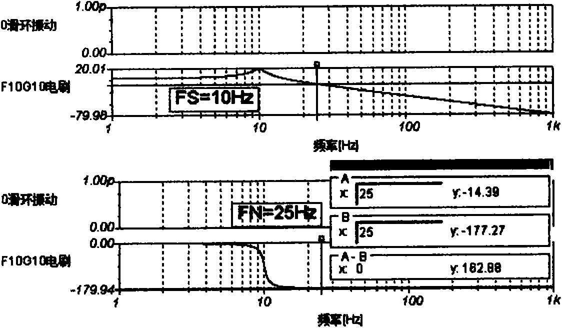
[0081] In this technical solution, the resonant frequency FS of the brush is designed to be greater than the highest excitation frequency FNH of the slip ring. If it is reversed, it will cause a strong impact. The simulation analysis is as follows:

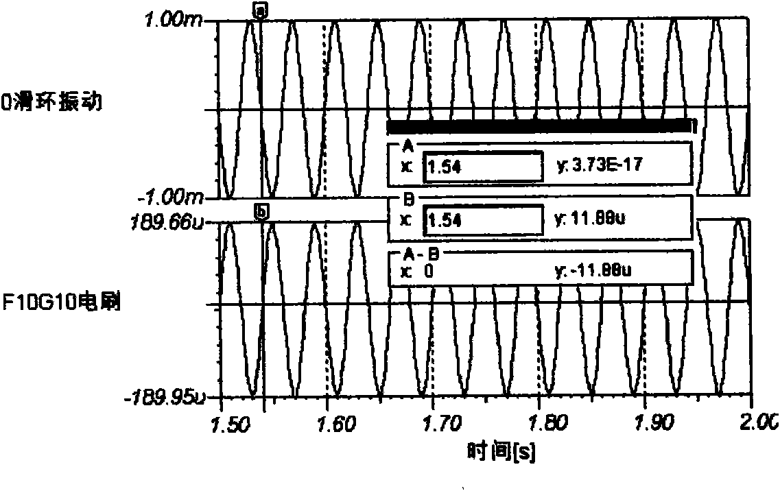
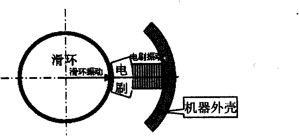
[0082] like Figure 6 It is a mechanical model simulation diagram for analyzing the interaction between slip ring vibration and FS=10Hz brush vibration, and Figure 4 The main difference is that the resonant frequency of the brush is changed from 100Hz to 10Hz, and "F10G10 brush" is used instead of "F100G10 brush". The resonant frequency of the described brush is FS=10Hz, the resonant gain G=10, and the forcing effect of the slip ring on the brush is 1mm. The opening amount of switches SW1~SW3 is 10n, and the closing amount is 0; the opening amount of switches SW4~SW6 is -10n, and the closing amount is 0; The "ring drive brush" impact when the positive vibration of the slip ring has a greater tendency than the positive vibrati...

Embodiment 2

[0112] Example 2: Uniformly distributed brushes and a non-faulty slip ring produce an impact equal to the number of brushes S = 6 times the frequency under the excitation of the first-order vibration frequency FN of the slip ring

[0113] Figure 12-1 It is a schematic diagram of the brush distribution structure of the AS19 wind turbine. The brush slip ring is not known to have failed. According to the fault diagnosis method of this patent technology, it is speculated that the brush should have an S-order prominent shock spectrum of the rotational speed frequency FN. Detected with the vibration and resonance demodulation fault diagnosis instrument 2 with brush slip ring fault diagnosis software manufactured according to this patented technology, it is found as follows:

[0114] One of the obtained data and the spectrum obtained from the analysis is as follows: Figure 12-2 , there are 6 clusters of shock pulses in one rotation cycle. The prominent spectral line frequency F...

Embodiment 3

[0118] A shaft voltage detection sensor 3 for detecting the failure of the brush slip ring in this scheme is a "shaft voltage pulse signal detection sensor" that detects the appearance of the insulated bearing seat of the shaft where the slip ring is located relative to the machine shell to which the brush is connected. Its feature is that it contains the signal line 3-1 connected to the bearing seat and the ground line 3-2 connected to the machine shell, such as Figure 13 "Schematic diagram of shaft voltage detection", and resistors R12~R15, capacitor C11, diodes SD1, SD2 and power supply VDD, NGND, signal line 3-1 is connected to one end of resistor R12, and the other end of R12 is connected to resistor R13 One end of C11 and the negative end of C11, the positive end of C11 is connected to one end of the resistor R15 and the negative end of the diode SD1, the positive end of SD2 and the other end of the resistor R15 are connected to the power supply VDD, and the positive end...


PUM


Abstract

A device for fault diagnosis of electric brush slip ring and method for mechanism diagnosis and maintenance and design are provided. The device for fault diagnosis of electric brush slip ring comprises at least one or more vibration shock sensors and / or shaft voltage detection sensors fixed on the machine casing of the electric brush, and a vibration and resonance demodulation fault diagnostic apparatus having diagnostic software for fault of electric brush slip ring and connected with the vibration shock sensors and / or shaft voltage detection sensors; the diagnostic software for fault of electric brush slip ring is used for analyzing the signals obtained by the vibration shock sensors and identifying the fault of the electric brush slip ring; and the vibration and resonance demodulation fault diagnostic apparatus has a vibration detection channel, a resonance demodulation detection channel and a computer having an AD converting acquitter and diagnostic software, wherein the detection signals of the vibration shock sensors and / or shaft voltage detection sensors are connected to the output end of the vibration detection channel and resonance demodulation detection channel; the output vibration and shock signals of the vibration detection channel and resonance demodulation detection channel are connected to the AD input end of the computer having an AD converting acquitter and diagnostic software; and the diagnostic software of the computer is for diagnosing fault, analyzing fault mechanism and determining maintenance and improved design for the acquired information.

Description

technical field [0001] The invention relates to a diagnosis device and a mechanism diagnosis and maintenance design method for a brush slip ring fault, belonging to the technical field of fault diagnosis and safety; especially suitable for brush slip rings such as double-fed generators of wind power generators and rail transit grounding circuits. Ring operation fault and structural fault diagnosis and treatment. Background technique [0002] Among the existing wind power generators, doubly-fed generators occupy the mainstream position; among them, "brush doubly-fed generators" with brush slip rings occupy a large proportion. A large number of brush slip ring failures occur in such generators, which may cause automatic tripping to stop power generation, or cause strong damage and seriously damage the safety of wind turbines. In other alternators, in order to prevent the shaft voltage induced by the rotor from flowing through and damaging the bearing, it is required to insula...

Claims


Application Information

Patent Timeline
IPC IPC(8): H02K15/00G01M13/00G01M1/22G01B17/06
Inventor 唐德尧曾承志
Owner 北京唐智科技发展有限公司
Learn More