Method and mould for manufacturing valve retainer

A manufacturing method and technology of valve seat rings, applied in the direction of manufacturing tools, casting molding equipment, furnace types, etc., can solve the problems of increased equipment and labor force, easy deviation, uneven top and bottom of tubular blank castings, etc., to reduce equipment investment and Effects of energy consumption, prevention of inclination and deformation, shortening of production cycle

Inactive Publication Date: 2009-12-02
张永炤 +1
View PDF0 Cites 8 Cited by
  • Summary
  • Abstract
  • Description
  • Claims
  • Application Information

AI Technical Summary

Problems solved by technology

The mold used is a cylindrical mold, and a columnar mandrel is fixed in the center of the cylindrical mold. After casting and demoulding, a tubular blank casting is obtained, which is cut and processed to obtain a valve seat ring. However, the use of this mold will cause the following problems: due to the high processing accuracy requirements for the valve seat ring, the requirements for the central core mold of the cylindrical mold are also very high, that is, the outer cylindrical surface of the cylindrical core mold is required to be relatively uniform as a whole, and the installation The core mold needs to be accurately positioned, and the position of the core mold is often prone to deviation during the casting process, which causes the center hole of the cast tubular blank casting to deviate from the central axis, and also causes uneven wall thickness of the valve seat ; Secondly, when casting the cylindrical mold, the amount of casting at one time is large, and it is easy to generate air bubbles during the casting process, which makes the produced tubular blank castings produce local defects, and the molten metal is easy to make after casting under the action of gravity. The tubular blank castings are uneven up and down, prone to inclination and deformation
After the above-mentioned machining operations of chip head, boring inner hole, and outer circle removal, it is necessary to cut the tubular blank casting horizontally and then grind it to obtain a valve seat ring that meets the production requirements. Therefore, the production steps are relatively cumbersome. , the equipment and labor required to be invested are greatly increased, and the tubular blank casting needs to be corrected in the subsequent mechanical processing, which greatly prolongs the production cycle and greatly increases the production cost, thus affecting the market competition of the final valve seat ring force

Method used


Image

  • Method and mould for manufacturing valve retainer
  • Method and mould for manufacturing valve retainer
  • Method and mould for manufacturing valve retainer

Examples


Embodiment 1

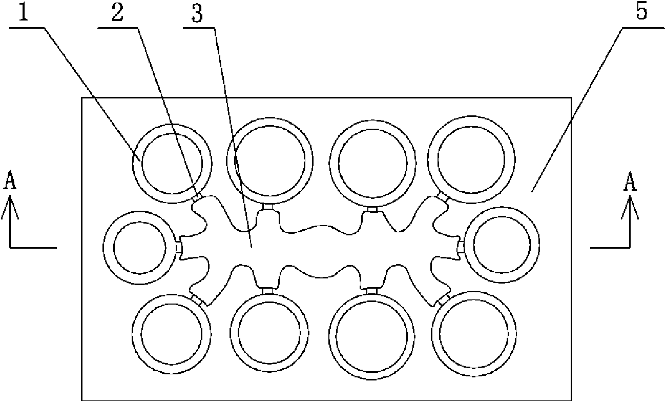
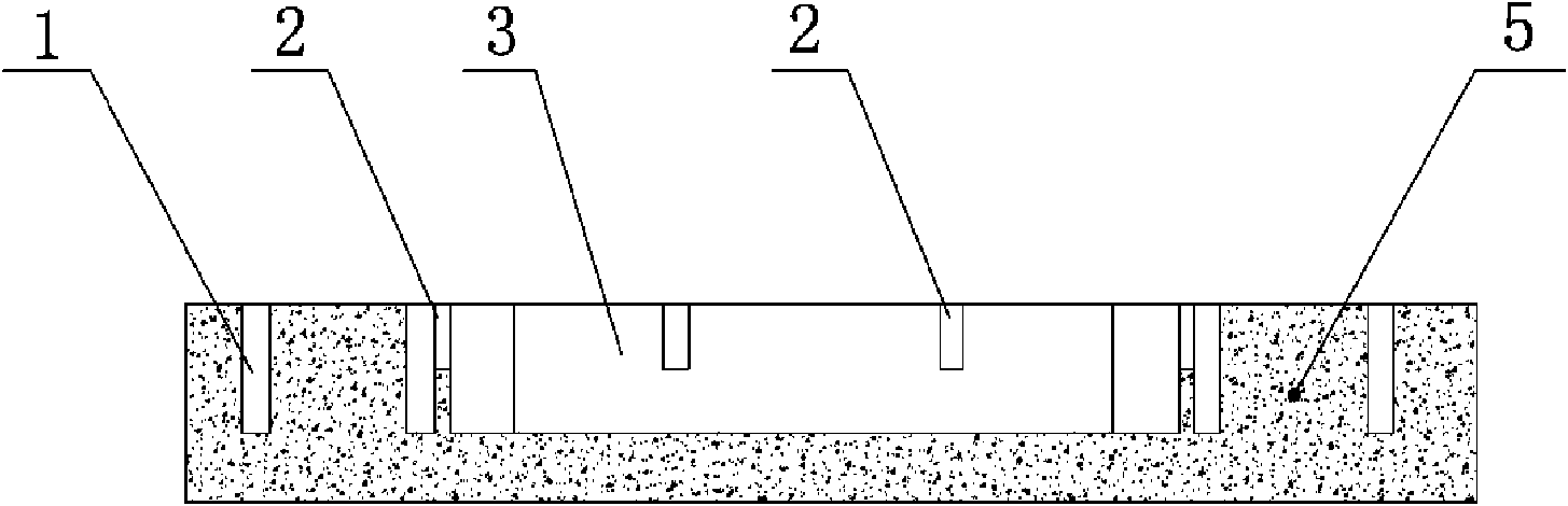
[0021] The direct forming mold of the valve seat ring of the present embodiment, as figure 1 , 2 As shown, the direct forming mold for the valve seat includes a disc-shaped body 5, on which a plurality of annular grooves 1 are opened, and the disc-shaped body 5 is also provided with a guide groove 3, the guide The runner 3 is connected with all the annular grooves; there is a shut-off 2 at the connection between the diversion groove 3 and the annular groove 1. The function of the shut-off is to make the valve seat ring easy to remove from the casting body after demoulding, and at the same time It also facilitates the grinding of the gate of the valve seat ring.

[0022] The specific steps of the manufacturing method of the valve seat ring of the present embodiment are as follows:

[0023] (1) Install the gate on the mold: seal the top of the valve seat ring directly into the mold, and install the gate to communicate with the diversion groove of the mold;

[0024] (2) smelti...

Embodiment 2

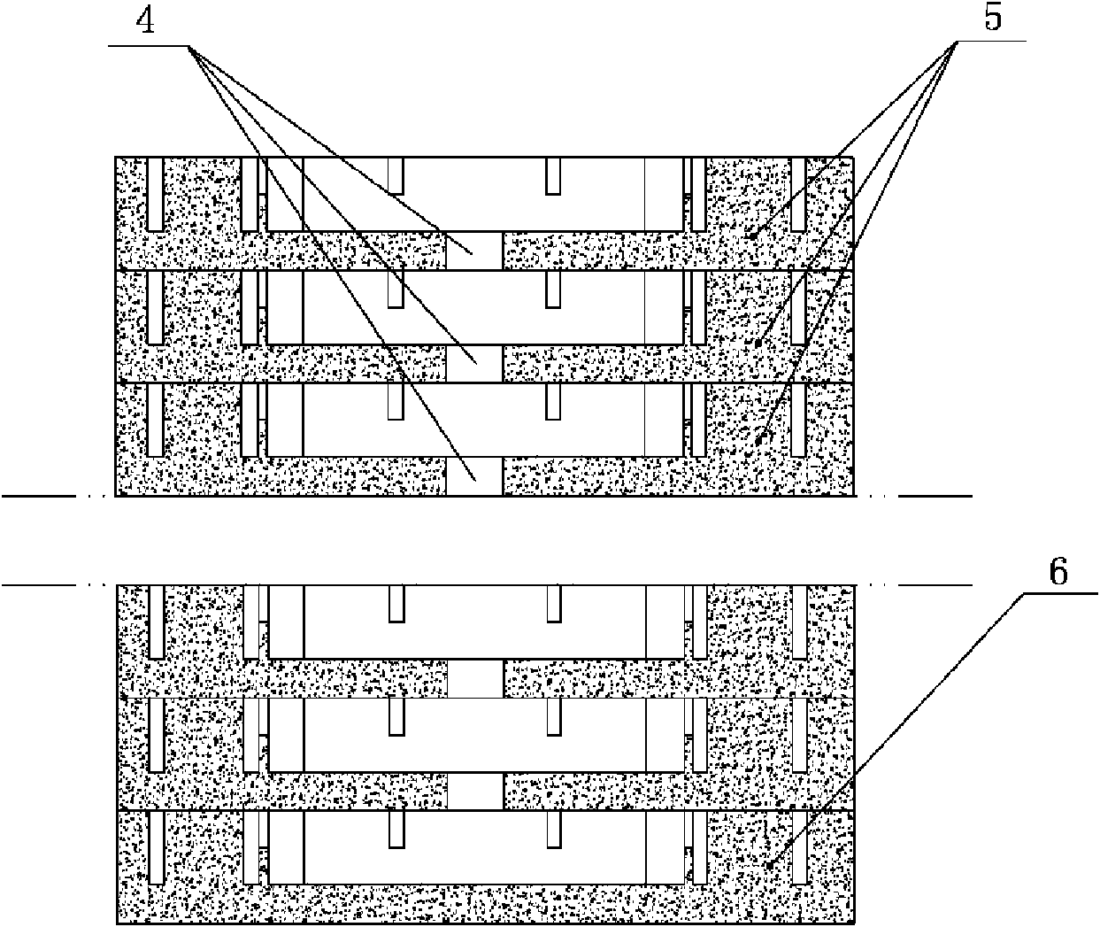
[0029] The manufacturing method of the valve seat ring of the present embodiment is the same as embodiment 1, the difference is: as image 3 As shown, the mold used is formed by stacking several disc-shaped bodies 5 up and down, and the bottom of the diversion groove of the disc-shaped body 5 above the bottom disc-shaped body 6 is provided with communicating holes 4, Make the diversion grooves of each valve seat ring direct molding mold communicate with each other through the communication holes, ensure that the upper and lower disc-shaped bodies are aligned when installing the mold, and install the gate in the diversion groove of the uppermost mold during casting, using this implementation The mold of the example can cast multiple disc-shaped valve seat rings at one time, which increases the number of valve seat rings cast at one time and greatly improves the production efficiency.

Embodiment 3

[0031] The manufacturing method of the valve seat of the present invention and the direct forming mold of the valve seat used are the same as in Example 1, the difference is that the temperature used for casting is 1475°C, and the heat treatment is quenching at 965°C for 5 hours, and then at 700°C °C annealing for 5 hours.


PUM


Abstract

The invention discloses a method for manufacturing a valve retainer, which comprises the following steps: arranging a sprue on a mould; and carrying out smelting, casting, demoulding, heat treatment and ground finishing on metal, wherein the mould is a directly molded mould for the valve retainer. Compared with the prior manufacturing method, the method for manufacturing the valve retainer saves four steps of sliping a head, boring an inner hole, digging up an excircle and cutting off. Therefore, the method simplifies the production steps, saves a large amount of labors, reduces the equipment input and energy consumption, shortens the production cycle and reduces the production cost.

Description

technical field [0001] The invention relates to a manufacturing method of a valve seat ring, and also relates to a direct forming mold of the valve seat ring used in the manufacturing method. Background technique [0002] The valve seat ring is one of the important parts of the automobile engine. Its function is to ensure the smooth exhaust and sealing of the exhaust valve of the automobile engine. Therefore, the valve seat ring is required to have the characteristics of high temperature resistance, wear resistance and oxidation resistance. The material used is high chromium alloy, and it also has high requirements on the processing accuracy of the specifications and dimensions of the valve seat ring, and the allowable error is extremely small. With the development of science and technology, people have higher and higher requirements for the performance of engine valve seat rings, and technicians are constantly adjusting and optimizing the processing technology and casting t...

Claims


Application Information

Patent Timeline
Patent Type & Authority Applications(China)
IPC IPC(8): B23P15/00B22C9/22C21D9/40C21D1/18C21D1/26
Inventor 张永炤张永乐
Owner 张永炤
Why Eureka
Try Eureka