Method for joining dissimilar metals of steel product and light metal product

A technology of dissimilar materials and joining methods, applied in the direction of thin plate connection, shrinkage connection, connection members, etc., can solve the problem of large reduction in the strength of the heat-generating fusion part and HAZ, impossibility, and inability to easily make assumptions, etc., to achieve flatness Guaranteed effect

Inactive Publication Date: 2009-12-02
KOBE STEEL LTD
View PDF2 Cites 72 Cited by
  • Summary
  • Abstract
  • Description
  • Claims
  • Application Information

AI Technical Summary

Problems solved by technology

As a result, there is a causative problem that the thinner the aluminum alloy material is, the greater the reduction in strength of the heat-generating fusion zone and HAZ is.
[0009] Moreover, in the technologies of these two patents, in performing multi-point spot welding, there is a fatal defect that the aforementioned pins need to be sequentially supplied to the tip of the electrode.
That is, the extremely real problem that exists now is, also do not have such equipment and device or structure, thereby be difficult to the spot welding electrode front end of the automobile body assembly line that automatic welding robot constitutes in welding, as above-mentioned continuous and Short-term continuous supply of the aforementioned pin
In these patents, there is no specific disclosure of the method. In addition, such a specific method cannot be easily inferred anyway.
Moreover, because there is no such method, and for example, even if it is assumed, it will only become a rather complicated device, so it is almost impossible to realistically adopt the technology of these patents

Method used


Image

  • Method for joining dissimilar metals of steel product and light metal product
  • Method for joining dissimilar metals of steel product and light metal product
  • Method for joining dissimilar metals of steel product and light metal product

Examples


Embodiment Construction

[0048] Hereinafter, specific modes for implementing the present invention will be described with reference to the drawings. In addition, the following description will also focus on aluminum alloy materials among light alloy materials, but the case of magnesium alloy materials is basically the same as that of aluminum alloy materials.

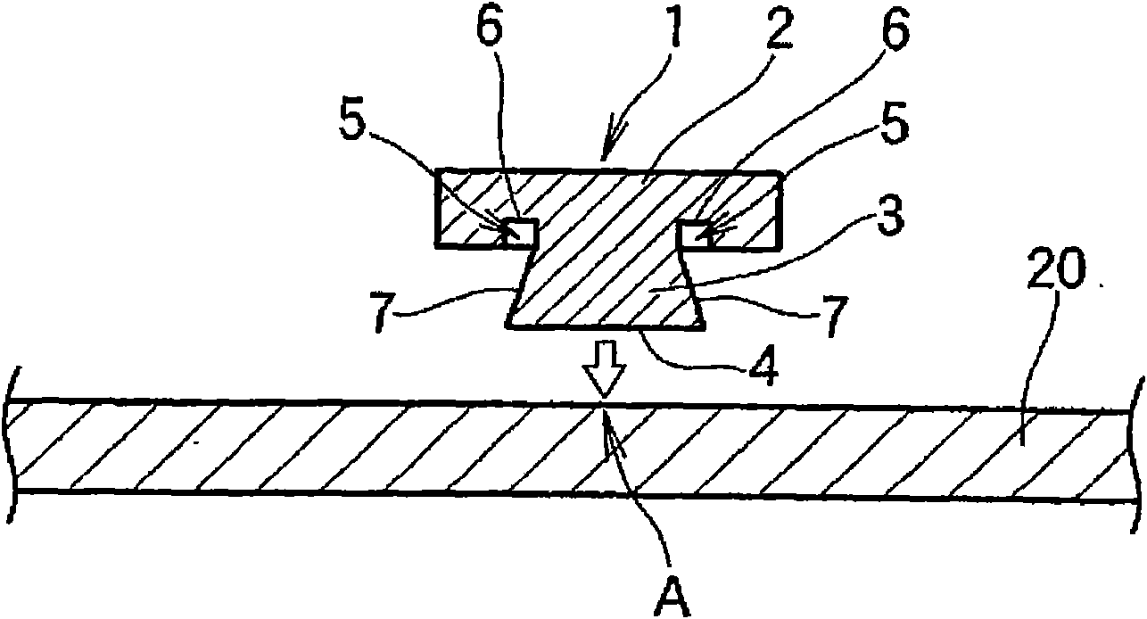
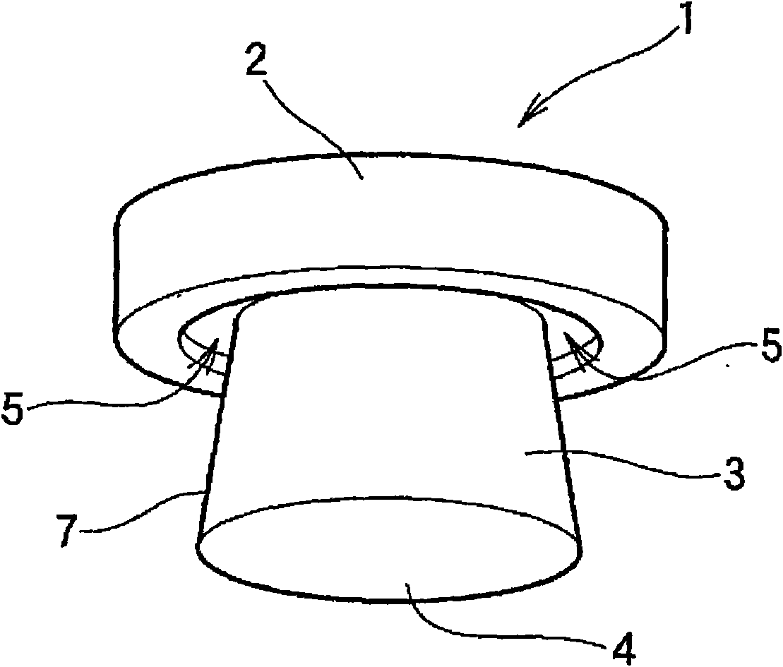
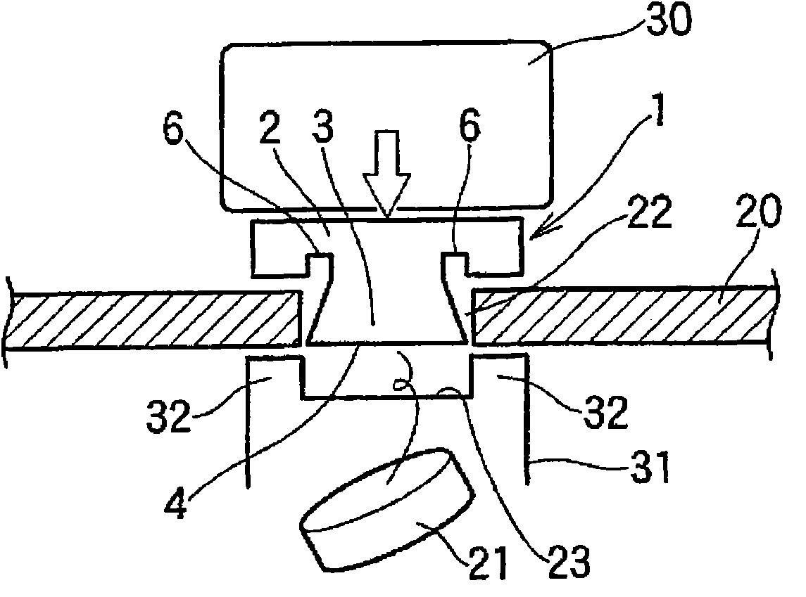
[0049] (The joining of iron rivets to aluminum alloy materials)

[0050] As a prerequisite, in the present invention, rivet joining and spot welding are used in combination to join dissimilar materials between steel materials and aluminum alloy materials. In this case, as the requirement a., it is the pre-process (other process) of the process of spot welding steel and aluminum alloy material, for example, in the press forming process of aluminum alloy material, the aluminum alloy material and the Iron-based rivets are mechanically joined in advance between aluminum-iron dissimilar materials. Then spot welding the rivet and steel.

[0051] (Joint o...


PUM

PropertyMeasurementUnit
tensile strengthaaaaaaaaaa

Abstract

There is provided method for joining dissimilar metals of a steel product and a light metal product with each other, wherein the light metal product and a rivet made of an iron-base metal are connected with each other beforehand in a previous process preceding spot welding, and subsequently, the rivet and the steel product are spot welded with each other. Then, a cavity for use in clinching the light metal product is formed, and upon the stem of the rivet is embedded into the light metal product to penetrate therethrough, light metal is caused to undergo plastic flow into the cavity of the rivet, for clinching the light metal product to be thereby clinched with the rivet whereupon spot welding for forming a weld nugget only within the scope of an interface between the stem of the rivet, and the steel product is carried out. Thus, the present invention can implement the spot welding between iron-iron similar metals, without a constraint on, and a problem with conditions applicable to the spot welding and a high joint strength can be obtained owing to the synergistic effect of the spot welding and connection by clinching of the aluminum alloy product with the iron-base rivet, added thereto.

Description

Technical field [0001] The present invention relates to a method for joining dissimilar materials of steel and light alloy materials. It is not between dissimilar materials such as aluminum and iron, but can be achieved by spot welding between the same materials such as iron and iron. The riveting of alloy materials and iron-based rivets utilizes this synergistic effect to obtain a method of joining dissimilar materials of steel materials and light alloy materials with high joint strength. In the present invention, the so-called light alloy materials refer to non-ferrous aluminum alloy materials, magnesium materials, and the like. Background technique [0002] The spot welding between the aluminum-iron dissimilar material of the steel and the aluminum alloy material generates the aforementioned fragile intermetallic compound in the joint portion, which causes a problem that the reliability of the welded portion is impaired. Therefore, even if it is a dissimilar material joining o...

Claims


Application Information

Patent Timeline
Patent Type & Authority Applications(China)
IPC IPC(8): B23P23/00F16B5/04B21D39/00B21J15/02B23K11/11B23K11/34F16B4/00F16B5/08
CPCB21J15/08B23P19/062B21J15/025B23K11/0066B23K11/20B23K2203/20B23K2103/20B23K2101/18
Inventor 岩濑哲今村美速
Owner KOBE STEEL LTD
Why Eureka
Try Eureka