Stress NMOS device and manufacturing method of stress CMOS

A manufacturing method and device technology, applied in semiconductor/solid-state device manufacturing, electrical components, circuits, etc., can solve the problems of complex manufacturing process adjustment, low carbon content, and small process window

Active Publication Date: 2011-05-04
SEMICONDUCTOR MANUFACTURING INTERNATIONAL (BEIJING) CORP
View PDF5 Cites 0 Cited by
  • Summary
  • Abstract
  • Description
  • Claims
  • Application Information

AI Technical Summary

Problems solved by technology

[0011] The invention provides a method for manufacturing a strained NMOS device to solve the problem of low carbon content in the existing process for forming a silicon carbide layer
[0012] The present invention also provides a manufacturing method of a strained CMOS device, so as to solve the problems that the manufacturing process adjustment of the existing strained CMOS is relatively complicated and the process window is small

Method used


Image

  • Stress NMOS device and manufacturing method of stress CMOS
  • Stress NMOS device and manufacturing method of stress CMOS
  • Stress NMOS device and manufacturing method of stress CMOS

Examples


Embodiment Construction

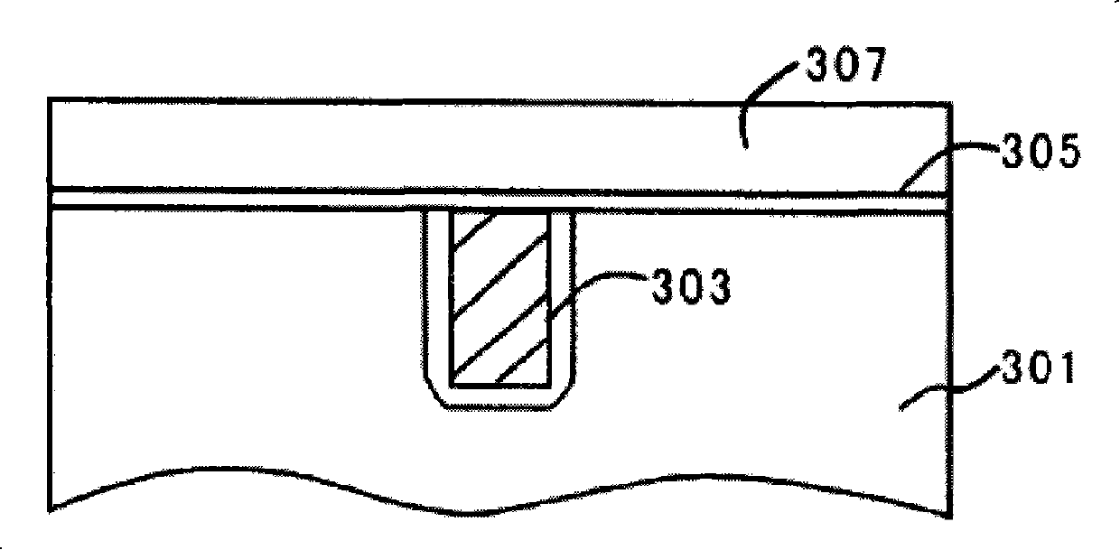
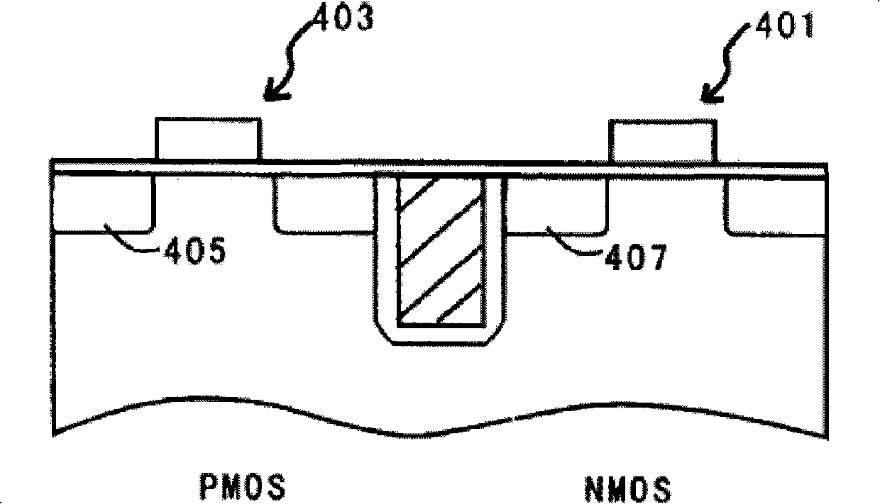
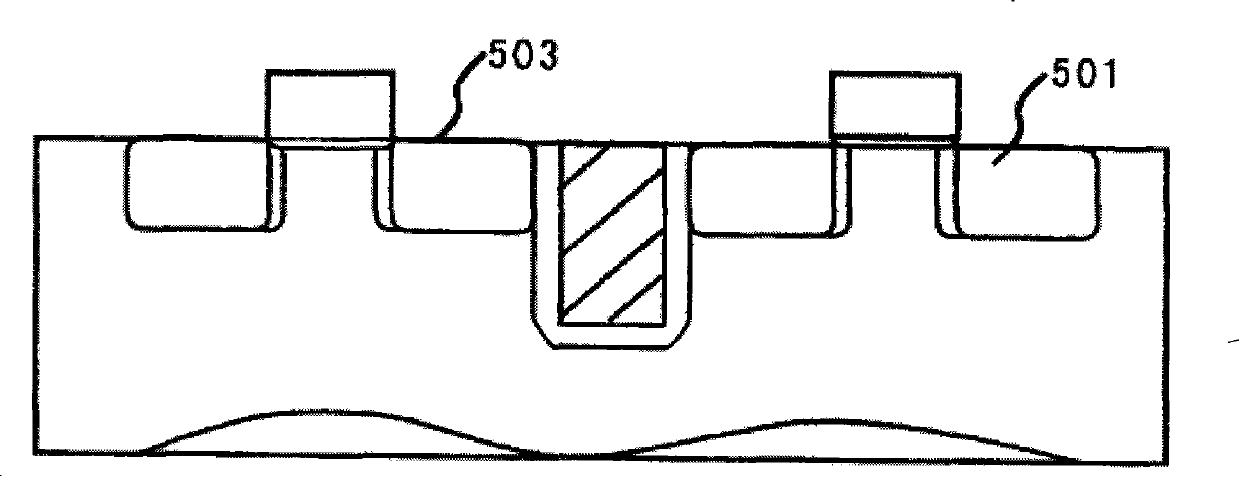
[0044] The specific embodiments of the present invention will be described in detail below in conjunction with the accompanying drawings.

[0045] In the following description, numerous specific details are set forth in order to provide a thorough understanding of the present invention. However, the present invention can be implemented in many other ways different from those described here, and those skilled in the art can make similar extensions without violating the connotation of the present invention, so the present invention is not limited by the specific implementations disclosed below.

[0046] Secondly, the present invention is described in detail using schematic diagrams. When describing the embodiments of the present invention in detail, for the convenience of explanation, the cross-sectional view showing the device structure will not be partially enlarged according to the general scale, and the schematic diagram is only an example, and it should not be limited here. ...


PUM


Abstract

A manufacturing method of a stress NMOS device comprises the followings: semiconductor substrates with grid structures are offered; a source electrode and a drain electrode are formed in the semiconductor substrates at two sides of the grid structures; wherein after the grid structures are formed and before the source electrode and the drain electrode are formed, or after the source electrode andthe drain electrode are formed, the method further comprises the following steps: ions are implanted, and carbon impurities are doped in the semiconductor substrates at two side of the grid structures; solid phase epitaxy process is carried out to facilitate the carbon impurities react with silicon to form a strain silicon carbide layer. The invention also provides a manufacturing method of the stress CMOS device. Carbon in the strain silicon carbide layer in the stress MOS device formed by the invention has comparatively high content, the stress applied to an NMOS conducting channel by an epitaxial layer of a silicon carbide material is greatly increased; the mobility of carriers can be effectively improved, thus enlarging the drive current and improving the performance of the NMOS device.

Description

technical field [0001] The invention relates to the technical field of semiconductor manufacturing, in particular to a manufacturing method of a strained N-type metal oxide semiconductor device (NMOS) and a strained complementary metal oxide semiconductor device (CMOS). Background technique [0002] The strained silicon technology can be applied in the manufacturing process of metal oxide semiconductor devices to improve the performance of the formed metal oxide semiconductor devices. For example, applying tensile stress (Tensile stress) in the conductive channel of N-type metal oxide semiconductor (NMOS) device can improve the electron mobility of the NMOS, and applying tensile stress in the conductive channel of P-type metal oxide semiconductor (PMOS) device Compressive stress can improve the mobility of holes. [0003] In the Chinese patent application document with the publication number CN 1941296A and the publication date being April 4, 2007, a manufacturing method of...

Claims


Application Information

Patent Timeline
Patent Type & Authority Patents(China)
IPC IPC(8): H01L21/336H01L21/265H01L21/8238H01L21/84
Inventor 吴汉明王国华
Owner SEMICONDUCTOR MANUFACTURING INTERNATIONAL (BEIJING) CORP
Why Eureka
Try Eureka