
Interleaved parallel PFC control circuit and control method

A control circuit and control method technology, applied in the direction of electrical components, high-efficiency power electronic conversion, output power conversion devices, etc., can solve problems such as high cost and complex control system, achieve product cost control, simple circuit structure, and reduce control The effect of system complexity

Active Publication Date: 2009-12-02
EMERSON NETWORK POWER CO LTD
View PDF0 Cites 40 Cited by
  • Summary
  • Abstract
  • Description
  • Claims
  • Application Information

AI Technical Summary

Problems solved by technology

[0007] However, both Scheme 1 and Scheme 2 have more sampling circuits for current detection. In Scheme 1, two currents are sampled, and in Scheme 2, three currents are sampled. This makes the control system complicated and costly to a certain extent. high

Method used


Image

  • Interleaved parallel PFC control circuit and control method
  • Interleaved parallel PFC control circuit and control method
  • Interleaved parallel PFC control circuit and control method

Examples


Embodiment Construction

[0047] The features and advantages of the present invention will be described in detail with reference to the accompanying drawings.

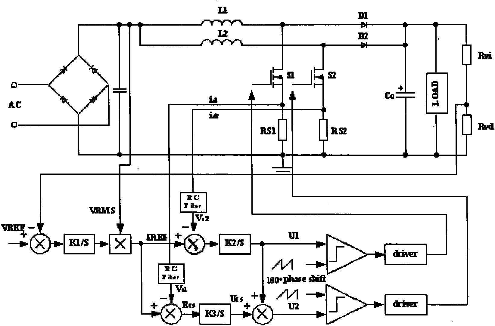
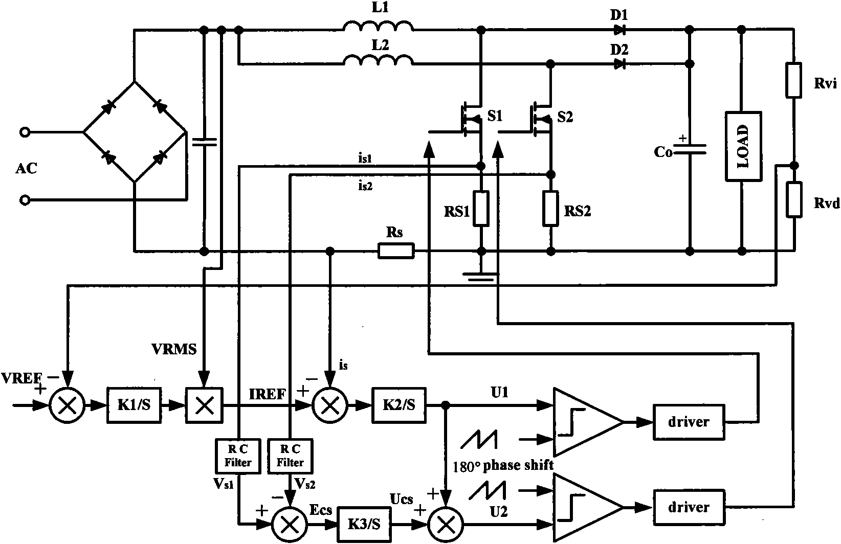
[0048] This embodiment is a specific application of the present invention in a boost (Boost) converter. The boost converter includes a main circuit and an interleaved parallel PFC control circuit, and the main circuit part includes a bridge rectifier circuit and a parallel PFC module. Such as Figure 4As shown, the interleaved parallel PFC control circuit includes a sampling module, a processing module, a comparison module, and a selection module. The sampling module is connected to the main circuit to perform signal sampling, and the selection module outputs a driving control signal to control the power switch of the parallel PFC module. Perform on-off control.

[0049] Please refer to Figure 5 , the parallel PFC module includes a first boost circuit and a second boost circuit, the first boost circuit includes a first inductor L1, a first d...


PUM


Abstract

The invention discloses an interleaved parallel PFC control circuit for controlling parallel PFC circuits, wherein a sampling module samples alternating current input voltage, PFC bus voltage and PFC bus current; a processing module processes the sampling signals and a reference voltage signal to generate a control signal; a comparing module compares the control signal with a first carrier signal and a second carrier signal to generate a first duty ratio signal and a second duty ratio signal, wherein the first carrier signal and the second carrier signal are interleaved by a specified phase angle and have the same wave shape; and a selecting module alternates the first duty ratio signal and the second duty ratio signal respectively according to the period thereof to be used as the driving control signal of one of two parallel PFC circuits to another to be output. The invention also discloses an interleaved parallel PFC control method. The invention can effectively avoid the problem of unbalanced current caused by asymmetrical driving signals of the prior interleaved parallel circuit, and has simple realization and low cost.

Description

【Technical field】 [0001] The present invention relates to a power factor correction (Power Factor Correction, hereinafter referred to as PFC) circuit, in particular to an interleaved parallel PFC control circuit and a control method. 【Background technique】 [0002] With the development of power electronics technology, the miniaturization and high power density of electronic equipment have become the embodiment of product competitiveness and technical level. Among them, parallel PFC technology has been developed rapidly. Parallel PFC technology enables the converter to distribute heat loss reasonably in each unit, improve unit reliability and power density, improve system fault tolerance and operational reliability, and reduce costs. However, the parallel connection of PFC circuits will make the ripple of the total current larger. An effective way to solve this problem is to adopt an interleaved operation mode for multiple parallel PFC units. The interleaved parallel techno...

Claims


Application Information

Patent Timeline
IPC IPC(8): H02M1/42
CPCY02B70/126Y02B70/10
Inventor 朱岩
Owner EMERSON NETWORK POWER CO LTD
Learn More