Hydraulic fertilizer device
A fertilization device and a hydraulic technology, applied in the field of agricultural irrigation, can solve the problems of large variation in the concentration of fertilizer solution in a pressure-difference fertilization tank, difficulty in ensuring the uniformity of fertilization, and increase in energy consumption of an irrigation system, etc., so that the fertilization concentration is easy and not easy to leak. , the effect of simple structure
- Summary
- Abstract
- Description
- Claims
- Application Information
AI Technical Summary
Problems solved by technology
Method used
Image

Examples
Embodiment 1
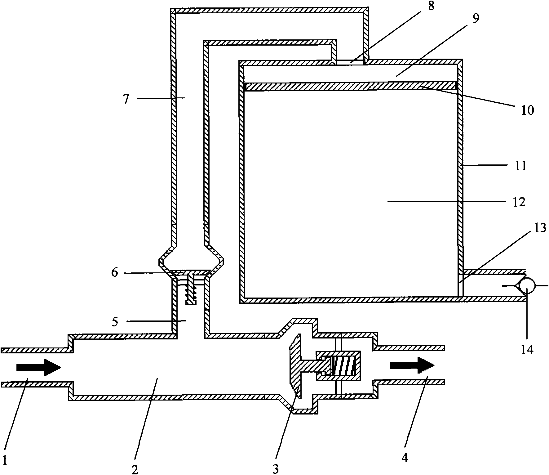
[0015] refer to figure 1 . The pulse generator is composed of water inlet pipe 1, pressure chamber 2, hammer valve 3, drain pipe 4 and water hammer pressure energy release pipe 5; pressure fertilizer storage tank 11, hydraulic thin plunger 10, hydraulic inlet 8, fertilizer injection port 13. The one-way valve B14 forms a hydraulic fertilization tank, and the hydraulic thin plunger 10 divides the pressure fertilizer storage tank 11 into a hydraulic tank 9 and a fertilizer tank 12. With the implementation of the fertilization process, the hydraulic tank 9 and the fertilizer tank 12 change dynamically , the hydraulic chamber 9 gradually expands, and the fertilizer liquid chamber 12 gradually shrinks; the pressure transmission assembly is composed of the one-way valve A6 and the hydraulic transmission pipeline 7; one end of the pressure transmission assembly communicates with the water hammer pressure energy release pipe 5 of the pulse generator, and the other One end communicate...
Embodiment 2
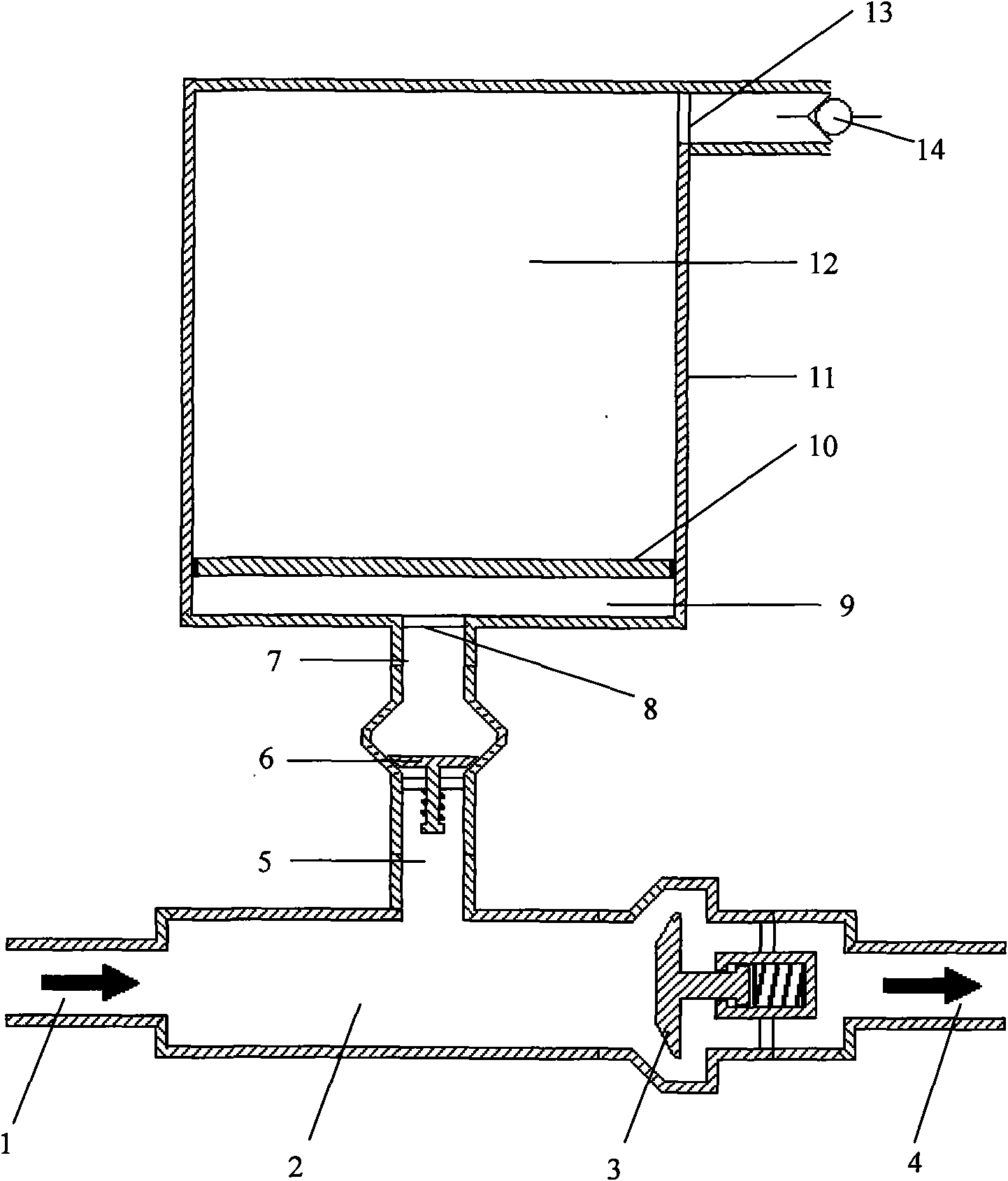
[0018] refer to figure 2 . The hydraulic fertilization device shown in embodiment 2 has similar basic structural features to embodiment 1, the difference is that the hydraulic fertilization tank is upside down, and the parts of embodiment 2 and embodiment 1 having the same structure are represented by the same reference numerals, which will not be repeated Be explained. The principle and implementation process of this embodiment are also the same as those of the first embodiment, so the description thereof is omitted.
[0019] The hydraulic fertilization device constructed in the present invention is used in parallel on the irrigation pipeline. When in use, the water inlet pipe 1 of the pulse generator is connected to the upstream end of the irrigation pipeline, and the fertilizer injection port 13 of the hydraulic fertilization tank is connected to the downstream end of the irrigation pipeline.
PUM
 Abstract
Description
Claims
Application Information
 - R&D
- Intellectual Property
- Life Sciences
- Materials
- Tech Scout
- Unparalleled Data Quality
- Higher Quality Content
- 60% Fewer Hallucinations
Browse by: Latest US Patents, China's latest patents, Technical Efficacy Thesaurus, Application Domain, Technology Topic, Popular Technical Reports.
© 2025 PatSnap. All rights reserved.Legal|Privacy policy|Modern Slavery Act Transparency Statement|Sitemap|About US| Contact US: help@patsnap.com