
Compound coal gasification system and method of blast furnace slags

A technology of slag gasification and blast furnace slag, which is applied in the direction of granular/powdered fuel gasification, joint combustion mitigation, recycling technology, etc. soil pollution etc.

Active Publication Date: 2009-12-09
NORTHEASTERN UNIV
View PDF0 Cites 22 Cited by
  • Summary
  • Abstract
  • Description
  • Claims
  • Application Information

AI Technical Summary

Problems solved by technology

At present, the water quenching method is basically used in domestic and foreign treatment of blast furnace slag. The disadvantage of this method is that not only the sensible heat of blast furnace slag cannot be used, but also a large amount of waste of water resources is caused, and serious pollution to the atmosphere, water and soil is also caused. working environment
Therefore, it is not feasible to base energy supply on the basis of oil like other countries. Although importing oil can also solve the energy shortage problem, such an energy strategy is not safe in terms of my country's current strength.

Method used


Image

  • Compound coal gasification system and method of blast furnace slags

Examples


Embodiment 1

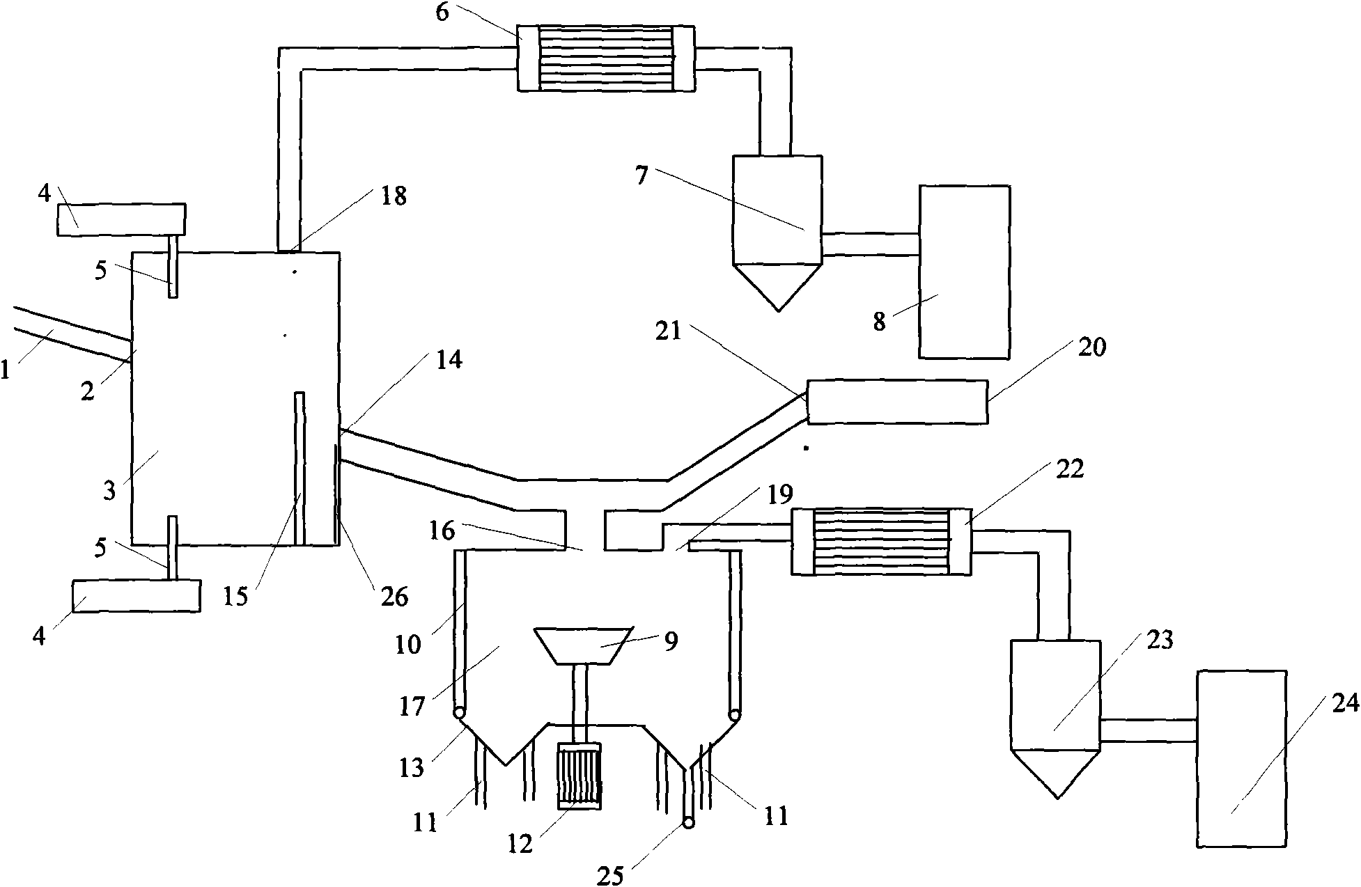
[0068] Blast furnace slag composite coal gasification system such as figure 1 As shown, it includes a slag gasifier 3, a heat exchanger 6, a gas dust collector 7, a gas storage tank 8, a coal feeding device 4, a spray gun 5, a secondary coal feeding device 20 and a particle gasifier 17; The furnace 3 has a diameter of 1m and a height of 1.5m. Its side wall is provided with a slag inlet 2 and a slag outlet 14 , a gas outlet 18 is provided at the top, and a partition wall 15 is provided inside. The height difference between the slag outlet 14 and the bottom of the slag gasifier 3 is 100mm. The diameter of the slag inlet 2 and the slag outlet 14 is 100mm, and the height difference between them is 500mm. Partition wall 15 is rectangular, and its two sides are connected with the side wall of slag gasifier 3, and its bottom edge is connected with the bottom of slag gasifier 3, and partition wall 15 height is 550mm; Partition wall 15 and slag The horizontal distance of the 3 axes o...

Embodiment 2

[0082] The blast furnace slag composite coal gasification system adopted is the same as in Example 1, the difference is that: (1) the diameter of the slag gasifier is 3m, and the height is 6m; the distance between the slag outlet and the bottom of the slag gasifier is 500mm, and the slag The height difference between the inlet and the slag outlet is 4m; (2) the horizontal distance between the axis of the slag gasifier and the partition wall is 1.2m; the height of the partition wall is 3m, (3) the spray gun inserted into the slag gasifier is 6 4 spray guns are located at the side of the slag gasifier, two spray guns are located at the bottom of the slag gasifier, the spray guns at the bottom are perpendicular to the horizontal plane, and the 4 spray guns at the side are distributed around the side, arranged in a tangential circle, and the spray guns are aligned with the horizontal plane The included angle is 15°; the diameter of the air outlets of the four spray guns on the side...

Embodiment 3

[0086] The blast furnace slag composite coal gasification system used is the same as that in Example 1.

[0087] The blast furnace slag gasification method is the same as in Example 1, the difference is: (1) when pulverized coal and gasification agent are blown into the slag gasification furnace through the spray gun, the gasification agent is water vapor, and within the same time, it enters the slag gasification furnace. The number ratio of the O atoms in the water vapor of the slag gasifier to the C atoms in the coal powder is 0.9-1.5. (2) The gasification agent injected into the particle gasifier through the bottom spray gun is water vapor, and the flow rate is 30m / s. At the same time, the O atoms in the water vapor and The number ratio of C atoms is 0.9-1.5.


PUM

PropertyMeasurementUnit
particle sizeaaaaaaaaaa

Abstract

A compound coal gasification system and a method of blast furnace slags relate to the blast furnace slag utilization technology. The system comprises a slag gasifier, a heat exchanger, a gas deduster, a gas storage tank, a coal feeding device, a spray gun, a secondary coal feeding device and a particle gasifier. The method comprises the following steps: the blast furnace slags are placed into the slag gasifier from a slag inlet through a slag runner; pulverized coal and gasifying agents are injected into the slag gasifier, the generated gas enters the heat exchanger, undergoes cooling and dedusting and then enters the gas storage tank; when flowing out of the slag outlet, the slags are mixed with the pulverized coal in a pipeline and react with the gasifying agents to generate gas which enters the heat exchanger, undergoes cooling and dedusting and then enters the gas storage tank. The method of the invention has enormous environmental benefits and is of significance to realize the national goal of energy conservation and emission reduction.

Description

technical field [0001] The invention relates to blast furnace slag utilization technology, in particular to a blast furnace slag composite coal gasification system and method. Background technique [0002] The iron and steel industry is an important basic industry of my country's national economy. China's iron and steel industry has developed rapidly since the 1990s. In 1996, my country's crude steel output has reached the first place in the world. With the growth of steel output, the solid waste produced by the iron and steel industry The total amount is also increasing, and among the solid waste, blast furnace slag accounts for a large proportion. Blast furnace slag is composed of gangue in iron ore, ash in fuel and non-volatile components in solvent. In the process of iron and steel production, the temperature of blast furnace slag is as high as 1400-1600 ° C. The sensible heat contained in it is It is equivalent to the heat generated by the complete combustion of 55Kg ~ ...

Claims


Application Information

Patent Timeline
Patent Type & Authority Applications(China)
IPC IPC(8): C21B3/06C10J3/48C10J3/46
CPCY02E20/18Y02W30/50
Inventor 秦勤李朋于庆波
Owner NORTHEASTERN UNIV
Learn More