
Combustion oxygenation device for automobile combustion engine

A technology of oxygen increasing device and internal combustion engine, applied in the direction of adding non-fuel substances to fuel, charging system, mechanical equipment, etc., can solve problems such as energy waste, black smoke from exhaust pipe, sudden power accidents, etc., and achieve improvement Oxygen content in the intake air, avoiding mechanical damage, and the effect of uniform and stable combustion

Inactive Publication Date: 2009-12-09
吴军杰
View PDF0 Cites 0 Cited by
  • Summary
  • Abstract
  • Description
  • Claims
  • Application Information

AI Technical Summary

Problems solved by technology

[0002] A large amount of CO and free carbon particles are produced in the tail gas of the existing automobile internal combustion engine, causing carbon deposits on the cylinder head, piston top, valve and spark plug, and black smoke from the exhaust pipe, which seriously pollutes the environment. Cause mechanical damage to the internal combustion engine and the occurrence of sudden power accidents
In order to improve the combustion efficiency of automobile internal combustion engines, supercharging technology is often adopted in this field to increase the intake air density and increase the intake air volume to achieve the purpose of increasing the oxygen content of internal combustion engines, but too much gas will cause more exhaust gas and pollution environment, a large amount of heat is taken away by non-gas, and after being discharged into the atmosphere, the waste of energy becomes more and more serious, and it makes it difficult to treat the exhaust gas

Method used


Image

  • Combustion oxygenation device for automobile combustion engine

Examples


Embodiment Construction

[0009] The content of the present invention will be further described below in conjunction with the accompanying drawings, but the specific implementation forms of the present invention are not limited to the following embodiments.

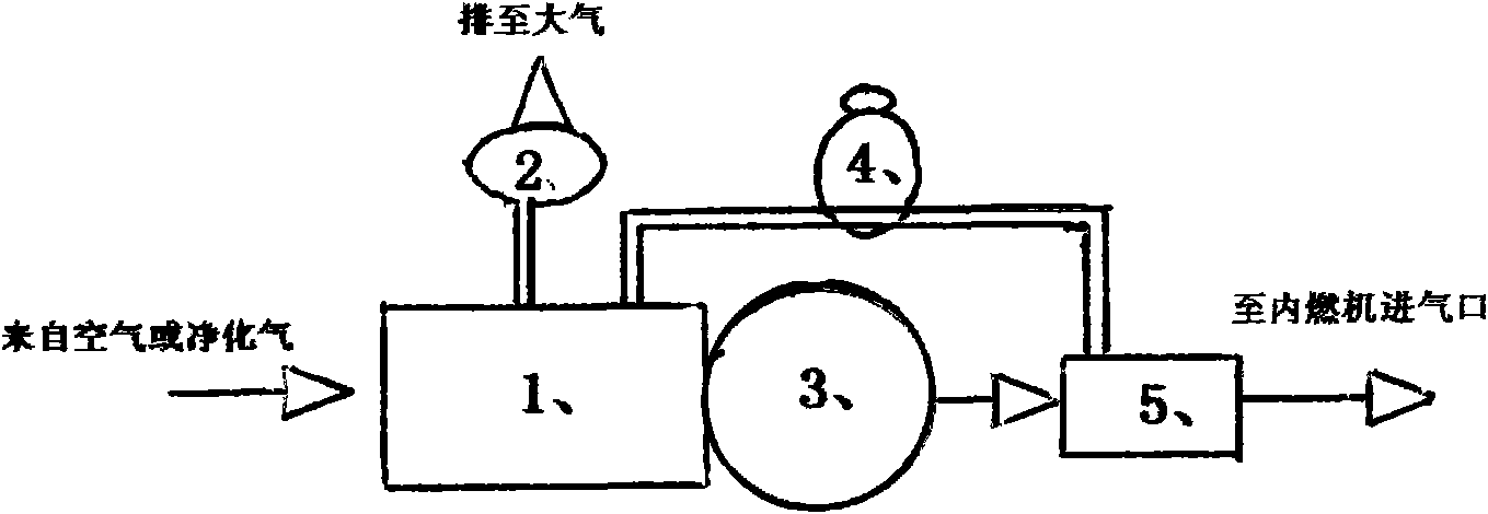
[0010] Referring to the accompanying drawings, the automobile internal combustion engine combustion aeration device of the present invention is composed of an air or purified gas collection chamber 1, a membrane oxygen separator 3, a gas mixing chamber 5, a decompression discharge check valve 2, and an oxygen content adjustment chamber. The valve 4 is composed of the gas collecting chamber 1, the membrane oxygen separator 3, and the gas mixing chamber 5, which are sequentially connected through pipe holes. The gas collection chamber 1 is provided with a gas discharge port leading to the decompression and discharge check valve 2. During operation, when the gas pressure or density in the gas collection chamber 1 rises to or exceeds the set air pressu...


PUM


Abstract

The invention relates to a combustion oxygenation device for an automobile combustion engine, composed of a gas collection cavity, a film type oxygen separator and a gas mixing cavity; wherein the gas collection cavity is provided with a discharge side of a reduced pressure discharge one-way valve, a connection pipe between the gas collection cavity and the gas mixing cavity is provided with a mixing cavity oxygen content control valve, and the outlet end of the gas mixing cavity is connected to an air inlet of the automobile combustion engine. Air or purified air flows into the gas collection cavity, oxygen rich gas in the air is separated by the oxygen film separator and is then sent into the mixing cavity to be adjusted to preset oxygen content and is further sent to the air inlet of the combustion engine, and the rest separated gas is remained in the gas collection cavity; when the pressure in the gas collection cavity exceeds the preset value, the reduced pressure discharge one-way valve is automatically opened to expel surplus gas in the cavity to the atmosphere; and when the oxygen content of gas in the mixing cavity is higher than the preset value, the mixing cavity oxygen content control valve is opened to induce the gas in the gas collection cavity into the mixing cavity, so as to adjust air inflow oxygen content while adjusting passage area of the film type oxygen separator.

Description

technical field [0001] The content of the present invention belongs to the technical field of internal combustion engine equipment for vehicles, and relates to a combustion oxygenation device for gas distribution safety of internal combustion engines of vehicles. Background technique [0002] A large amount of CO and free carbon particles are produced in the tail gas of the existing automobile internal combustion engine, causing carbon deposits on the cylinder head, piston top, valve and spark plug, and black smoke from the exhaust pipe, which seriously pollutes the environment. Cause the mechanical damage of internal combustion engine and the generation of sudden vicious accident of power. In order to improve the combustion efficiency of automobile internal combustion engines, supercharging technology is often adopted in this field to increase the intake air density and increase the intake air volume to achieve the purpose of increasing the oxygen content of internal combus...

Claims


Application Information

Patent Timeline
Patent Type & Authority Applications(China)
IPC IPC(8): F02M25/00
Inventor 吴军杰
Owner 吴军杰
Learn More