
Zero-voltage-switching (ZVS) full-bridge DC converter adopting passive auxiliary network

A technology of zero-voltage switching and DC converters, applied in the field of zero-voltage switching DC converters and zero-voltage switching full-bridge DC converters, can solve the problems of irrelevant load current, auxiliary energy loss, and lower efficiency, and achieve high conversion efficiency , the effect of reducing loss

Inactive Publication Date: 2009-12-16
NANJING UNIV OF AERONAUTICS & ASTRONAUTICS
View PDF0 Cites 13 Cited by
  • Summary
  • Abstract
  • Description
  • Claims
  • Application Information

AI Technical Summary

Problems solved by technology

There is a literature that adds a passive auxiliary network to the full-bridge converter, and uses the auxiliary inductor current to help the lagging bridge arm to achieve ZVS, but the auxiliary inductor current is constant. At full load, the energy stored in the resonant inductor can already realize the lagging bridge arm. ZVS, the auxiliary energy has a certain loss
[0004] The above various methods realize the ZVS of the lagging bridge arm to different degrees, but they have a common problem, that is, the auxiliary energy to realize the ZVS of the lagging bridge arm is basically unchanged and has nothing to do with the load current.
At full load, the energy stored in the resonant inductor can already realize the ZVS of the lagging bridge arm, and there is a certain loss of auxiliary energy, which reduces the efficiency

Method used


Image

  • Zero-voltage-switching (ZVS) full-bridge DC converter adopting passive auxiliary network
  • Zero-voltage-switching (ZVS) full-bridge DC converter adopting passive auxiliary network
  • Zero-voltage-switching (ZVS) full-bridge DC converter adopting passive auxiliary network

Examples


Embodiment Construction

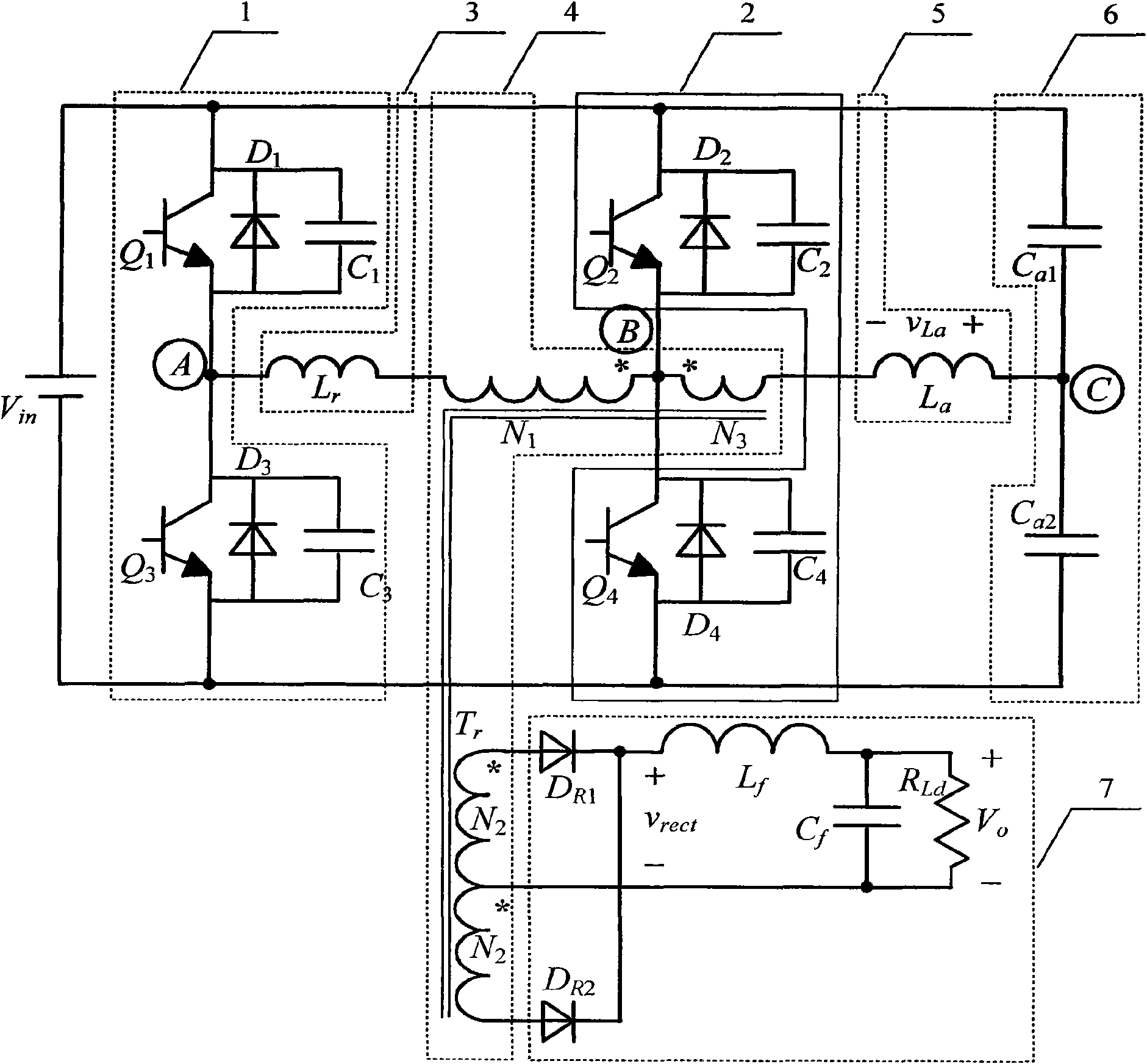
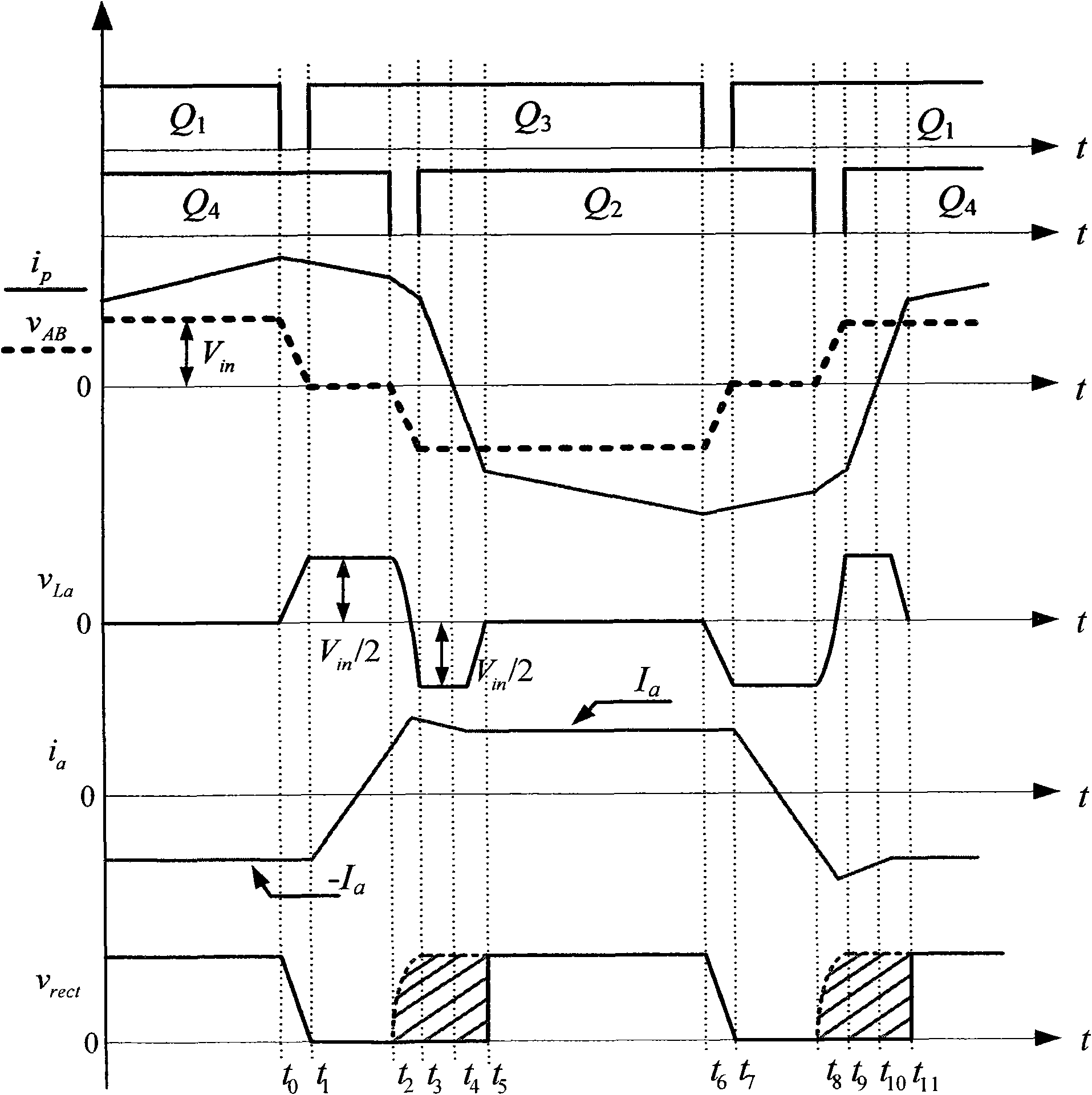
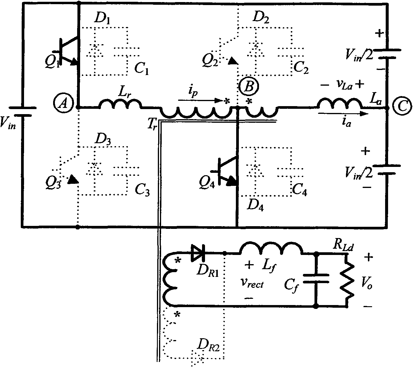
[0013] attached figure 1 Shown is a schematic diagram of the circuit structure of a zero-voltage-switching full-bridge DC converter using a passive auxiliary network. by the DC power supply V in , two inverter bridge arms 1 and 2, a resonant inductor 3, an isolation transformer 4, an auxiliary inductor 5, a voltage dividing capacitor 6, and a rectifier and filter circuit 7. Q 1 ~Q 4 are four main switch tubes, D 1 ~D 4 are the switching tube Q 1 ~Q 4 body diode, C 1 ~C 4 respectively switch Q 1 ~Q 4 The parasitic capacitance, L r is the resonant inductance, T r is the isolation transformer, L a is the auxiliary inductance, Ca 1 and Ca 2 are two voltage divider capacitors, D R1 and D R2 is the output rectifier diode, L f is the output filter inductor, C f is the output filter capacitor, R Ld for the load. The converter adopts phase-shift control, the switch tube Q 1 and Q 3 Respectively ahead of the switching tube Q 4 and Q 2 One phase, called switch tu...


PUM


Abstract

The invention provides a zero-voltage-switching (ZVS) full-bridge DC converter adopting a passive auxiliary network, comprising a DC power supply (Vin), a first inverter bridge leg (1), a second inverter bridge leg (2), a resonant inductor (3), an isolating transformer (4), an auxiliary inductor (5), a voltage-dividing capacitor circuit (6), a rectifier and filter circuit (7) and a primary auxiliary winding (N3); wherein, the primary auxiliary winding (N3), the auxiliary inductor (5) and the voltage-dividing capacitor circuit (6) form the passive auxiliary network. The DC converter not only realizes ZVS of switching tubes but also realizes ZVS of lagging leg switching tubes. The provided energy is in relation with the load current; when the load is heavy, the energy stored in the auxiliary inductor is less, and the energy stored in the auxiliary inductor gradually rises along with lightening of the load. Therefore, the DC converter on the one hand can reduce the loss brought about by the auxiliary network when the load is heavier and on the other hand can realize ZVS of the lagging leg switching tubes when the load is lighter.

Description

technical field [0001] The invention relates to a zero-voltage switch direct current converter, in particular to a zero-voltage switch full-bridge direct current converter, which belongs to the direct current converter in electric energy conversion devices. Background technique [0002] At present, many standards put forward strict requirements on power supply efficiency from the perspective of energy saving. It is hoped that the converter can still work efficiently in the entire load range, especially at light load. The zero-voltage-switching (ZVS for short) full-bridge converter with phase-shift control utilizes the leakage inductance of the transformer and the junction capacitance of the switch tube to realize the ZVS of the switch tube, and is widely used in medium and high power applications. Since the leakage inductance of the transformer is generally small, its energy is not enough to realize the ZVS of the lagging bridge arm at light load, and the efficiency of the c...

Claims


Application Information

Patent Timeline
IPC IPC(8): H02M3/28H02M3/335H02M7/5387
CPCY02B70/1441Y02B70/1433Y02B70/1491Y02B70/10
Inventor 陈武阮新波
Owner NANJING UNIV OF AERONAUTICS & ASTRONAUTICS
Learn More