
Optical sheet and manufacturing method of the same

A kind of manufacturing method, technology of optical sheet

Active Publication Date: 2009-12-30
KEIWA INCORPORATED
View PDF4 Cites 3 Cited by
  • Summary
  • Abstract
  • Description
  • Claims
  • Application Information

AI Technical Summary

Problems solved by technology

[0006] The conventional light-diffusing sheet of the above-mentioned particle-coated type uses the refraction and reflection caused by the particles 59 in the adhesive 58 when exhibiting diffusivity, so multiple scattering occurs, which inevitably causes a loss of light output.
In addition, for the particle-coated light-diffusing sheet, since the coating solution containing synthetic resin, particles, solvents, etc. is coated on the substrate layer and dried to form the light-diffusing layer, it is necessary to volatilize the solvent, thereby increasing the processing speed. Subject to certain restrictions
[0007] The above-mentioned embossed conventional light-diffusing sheet that adopts press molding has low production efficiency because of the batch type, and there is a problem that it cannot be quite thin.
In addition, the above-mentioned embossed light-diffusing sheet by extrusion molding using an embossing roll is difficult to form a precise concave-convex shape, and there is a problem of poor optical characteristics.

Method used


Image

  • Optical sheet and manufacturing method of the same
  • Optical sheet and manufacturing method of the same
  • Optical sheet and manufacturing method of the same

Examples


Embodiment

[0117] Hereinafter, the present invention will be described in detail according to examples, but the present invention is not limited by these examples.

[0118] Example

[0119] Containing 100 parts of acrylic polyol ester ("NK ester" manufactured by Shin-Nakamura Chemical Industry Co., Ltd.; solid content 50%), isocyanate ("Corone-to HL" manufactured by Nippon Polyurethane Industry Co., Ltd.), solid content 75%), 105 parts of methyl ethyl ketone, and 105 parts of toluene, 130 parts of acrylic acid particles (manufactured by Sekisui Chemical Industry Co., Ltd. "MBX-12") with an average particle diameter of 12 μm were mixed to prepare Coating liquid for forming an optical layer, the coating liquid for optical layer is coated on the surface of a substrate film for an original plate made of transparent polyethylene terephthalate with a thickness of 188 μm at a rate of 11 g / m 2 (Converted to solid content), the original optical sheet was obtained.

[0120] Using the optical she...


PUM


Abstract

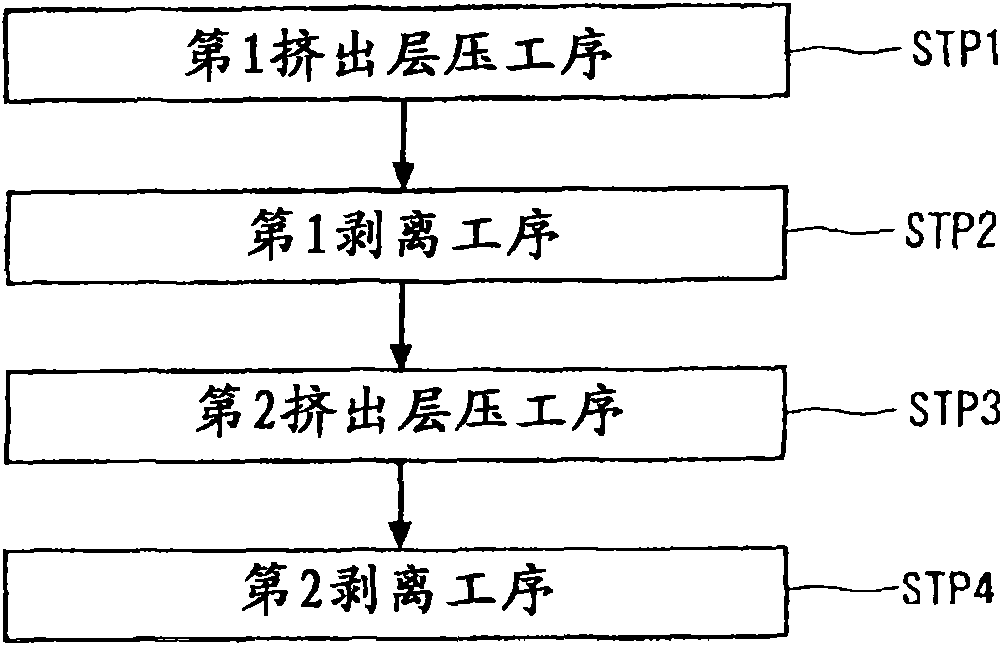
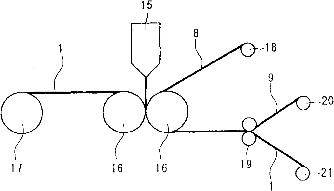
The invention aims to provide an optical sheet manufacturing method with high production efficiency, high all ray transmission, high optical performances such as photodiffusion function, ray concentration function and refraction function in normal direction capable of preventing plural scattering and an optical sheet using the manufacturing method. The optical sheet manufacturing method comprises: a first extruding laminating working procedure: an original optical sheet with the same shape as the surface having micro concavo-convex optical sheet is used, a synthetic resin for molding is laminated by using extruding laminating method on the surface of the original optical sheet; a first peeling working procedure: from the synthetic resin for molding, the original optical sheet is peeled to prepare an optical sheet forming mold transferred with reversed shape with the micro concavo-convex shape on the surface; a second extruding laminating working procedure: the synthetic resin for optical layer is laminated by using extruding laminating method on the surface of the optical sheet forming mold; and a second demolding working procedure: the optical sheet forming mold is peeled from the synthetic resin layer for optical layer to prepare the optical sheet transferred with the micro concavo-convex shape on the surface.

Description

technical field [0001] This invention relates to the manufacturing method of the optical sheet used for a liquid crystal display device etc., and the optical sheet manufactured by this manufacturing method. Background technique [0002] In a liquid crystal display device, a backlight system in which a liquid crystal layer is illuminated from the back to emit light has become popular, and an edge light type, vertical type, or other backlight unit is mounted on the lower surface of the liquid crystal layer. The edge light type backlight unit 50 is basically as Figure 10 As shown, there are a linear lamp 51 as a light source, a square plate-shaped light guide plate 52 arranged along the end of the lamp 51 , and various optical sheets arranged on the surface side of the light guide plate 52 . As this optical sheet, it corresponds to the light-diffusion sheet 53 arrange|positioned on the front side of the light guide plate 52, the prism sheet 54 etc. which are arrange|positioned...

Claims


Application Information

Patent Timeline
IPC IPC(8): B29C47/00G02F1/1335B29C48/305
CPCG02B5/0268G02B5/0231B32B27/08G02F1/133606B29C48/08
Inventor 长村惠弌小林俶朗冈部元彦峯尾裕
Owner KEIWA INCORPORATED
Learn More