
Large-cyclotron electron gun with axial signal input of cusped magnetic field

A signal input and cusp magnetic field technology, applied in the field of electron guns, can solve the problems of inconvenient design of high-performance cyclotron maser devices, increase the difficulty of design and processing technology, increase the radius and volume of the cyclotron amplifier, and overcome the signal input mode Complexity, signal input method and structure are simple, miniaturization reduces the effect

Inactive Publication Date: 2010-01-06
UNIV OF ELECTRONICS SCI & TECH OF CHINA
View PDF0 Cites 3 Cited by
  • Summary
  • Abstract
  • Description
  • Claims
  • Application Information

AI Technical Summary

Problems solved by technology

This type of cyclotron amplifier performs the generation of the initial electron beam and the signal input in two relatively independent parts. Although the electron gun has the characteristics of simple structure, single function, and good laminar flow of the initial electron beam; The horizontal input signal is used in the resonant cavity (interaction section), so the waveguide for signal input must be arranged radially on the outer ring surface of the resonant cavity, which not only increases the radius and volume of the cyclotron amplifier, making it difficult to miniaturize , which also increases the difficulty in the design and processing of peripheral devices such as superconducting permanent magnets and their circulating cooling systems, and also brings a lot of inconvenience to the design of high-performance gyrotron devices
Therefore, the above-mentioned electron gun has a single function, and can only be matched with a resonant cavity (interaction section) provided with a transverse (signal input) waveguide to form a cyclotron amplifier, and the manufactured cyclotron amplifier (maser) is large in size and difficult to Miniaturization, but also brings difficulties to the design of high-performance swing amplifiers, etc.

Method used


Image

  • Large-cyclotron electron gun with axial signal input of cusped magnetic field

Examples


Embodiment Construction

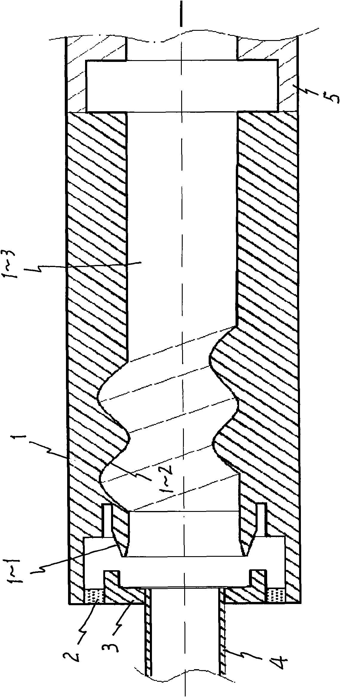
[0009] In this embodiment, an electron gun for coaxial millimeter wave signal input is taken as an example: the electron gun body (anode) 1 has an axial length of 91.6mm and an outer diameter of φ28.6mm, the anode head 1-1 has a port diameter of φ14.8mm, and the mode conversion mechanism 1- 2 is a spiral conversion mechanism with 2 pitches (wave bands), 2 times the perturbation radius of each groove surface is 3.6mm, the pitch (that is, the length of each band) 12.8mm, the transition section (cavity) 1-3 diameter φ13.8mm The ceramic ring 2 has a thickness of 2.7mm, an outer diameter of φ25.0mm, an inner diameter of φ20.0mm, an outer diameter of the cathode 3 of φ25.0mm, an axial length of 12.0mm, a center hole diameter of φ10.0mm that matches the waveguide 5, and an inner diameter of the waveguide 5 φ6.4mm.

[0010] The main working principle of the large cyclotron electron gun of this embodiment: the ring-shaped cathode of the electron gun, its emission band produces a hollow no...


PUM


Abstract

The invention relates to an electron gun matched with a cyclotron amplifier in the technical field of microwaves, which comprises an electron gun body used as an anode, an anode head, a mode conversion mechanism, a transition section, a cathode and a ceramic ring, wherein the anode head, the mode conversion mechanism and the transition section are arranged in the electron gun body; the cathode is arranged at the rear end of the gun body and shares the same axle line with the gun body; the ceramic ring is used for connecting the cathode and the gun body into a whole; and the cathode is also provided with a central hole and a waveguide tube which is connected with the central hole and used for signal input. The electron gun can generate an electron bunch with good performances of large working speed ratio and small electron bunch fluctuation and speed scatter and can also carry out dual functions of microwave input mode conversion and improve the conversion efficiency of the mode. Moreover, when the electron gun is matched with a resonant cavity, the electron gun can greatly improve the structure of the cyclotron amplifier so as to ensure that the cyclotron amplifier has the characteristics of simple signal input mode and structure, small volume, high conversion efficiency, lower requirement on the intensity of a working magnetic field, realization of the miniaturization of the cyclotron amplifier, effective reduction of the design difficult of a high-performance cyclotron maser device, and the like.

Description

Technical field [0001] The invention belongs to an electron gun matched with a cyclotron amplifier (a cyclotron maser) in the technical field of microwave and millimeter waves, and particularly relates to an electron gun equipped with an axial (microwave, millimeter wave) signal input wave guide and a cleavable magnetic field and a large cyclotron electron gun. Background technique [0002] As a new type of high-power millimeter wave and sub-millimeter wave device, the cyclotron amplifier has been developed rapidly since its inception. The series of cyclotron devices have been successfully developed. Its wave band has reached the millimeter wave and sub-millimeter wave band, and the power is as high as several megawatts. It has reached hundreds of kilowatts. In the millimeter wave band, this is unmatched by ordinary microwave tubes. However, when the cyclotron amplifier further develops to a higher frequency band, due to the narrower frequency band, low conversion efficiency and ...

Claims


Application Information

Patent Timeline
Patent Type & Authority Applications(China)
IPC IPC(8): H01J25/02H01J23/06H01J23/00
Inventor 赵青孙旭吴浠桥刘建卫
Owner UNIV OF ELECTRONICS SCI & TECH OF CHINA
Learn More