
Household biomass gasifier

A biomass and gasifier technology, which is applied to household stoves/stoves, household appliances, household heating, etc., can solve the problems of small gas production, unfavorable maintenance, and narrow use, and achieves increased gas calorific value, simplified structure, Emission reduction effect

Inactive Publication Date: 2010-01-20
KUNMING DIANYAN NEW ENERGY TECH DEV
View PDF0 Cites 2 Cited by
  • Summary
  • Abstract
  • Description
  • Claims
  • Application Information

AI Technical Summary

Problems solved by technology

[0002] At present, although the existing coal gasifiers and biomass gasifiers can provide coal gas and biomass gas, the types of fuel are single, the purpose is narrow and the gas production is small, it is difficult to ignite, the operation is difficult, and it cannot be used during power outages. A large amount of tar will be produced, which will cause serious environmental pollution. The tar will also damage the furnace itself, and the household biomass gasifier does not have a dedicated burner. The burners used in the current household biomass gasifier are generally for pipeline gas , liquefied petroleum gas, natural gas and other high calorific value gases, the pipes and burners are often blocked by tar during use, which is not conducive to maintenance, short service life, and the air intake and air ratio are not suitable for household biomass gasification The low calorific value gas produced by the furnace, therefore, it is necessary to innovate the existing technology to solve the above problems

Method used


Image

  • Household biomass gasifier
  • Household biomass gasifier
  • Household biomass gasifier

Examples


Embodiment Construction

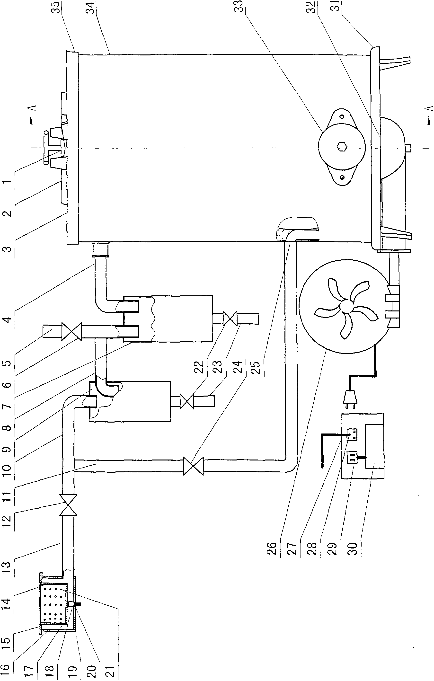
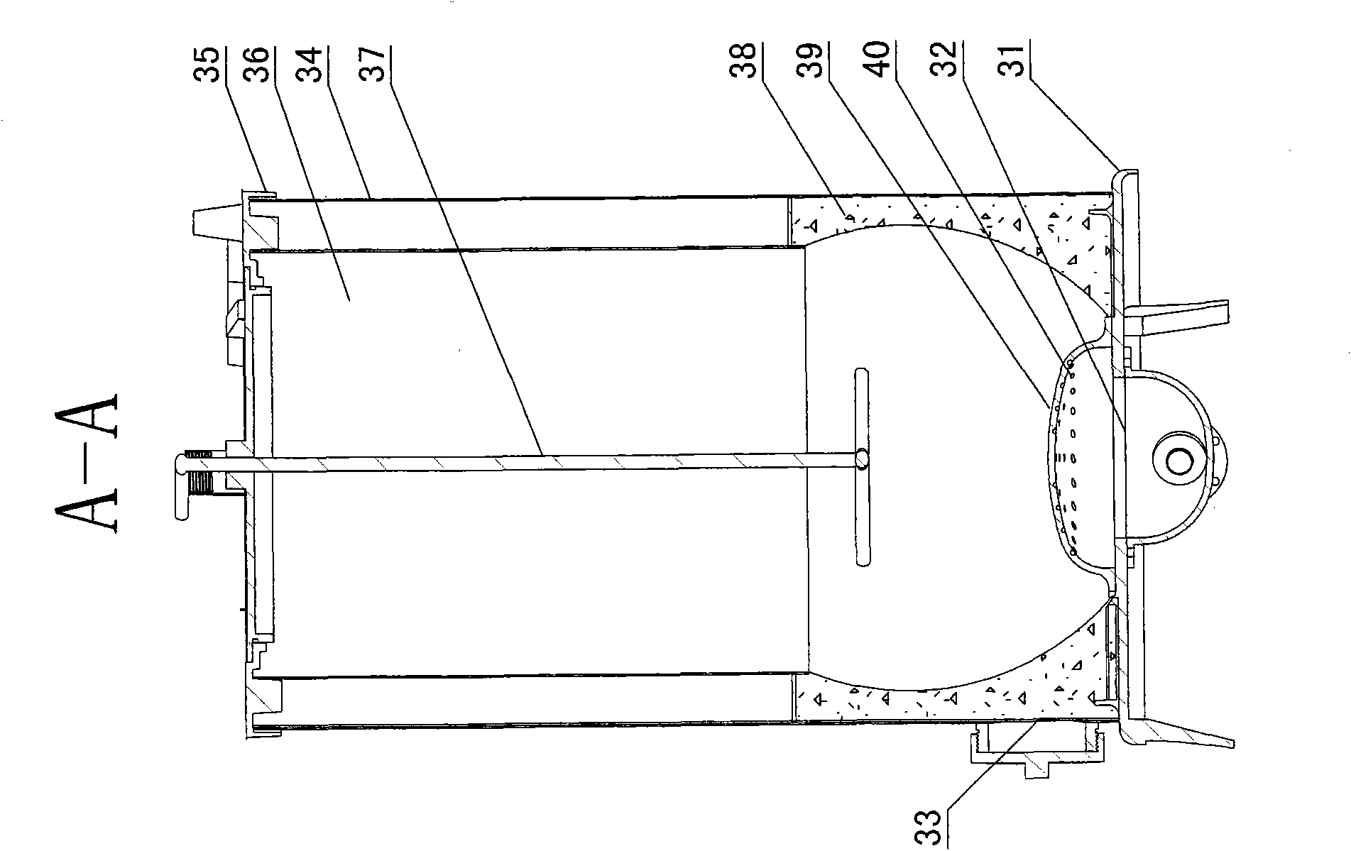
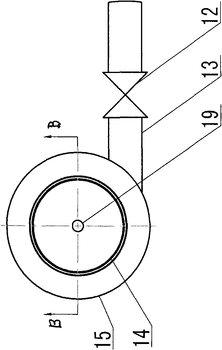
[0024] The household type biomass gasification furnace proposed by the present invention is combined with the following Figure 1-4 Further details.

[0025] As shown in the figure, there is a cylindrical fuel gasification chamber 36 in the body of the furnace. The gasification chamber is surrounded by a furnace gall formed by a high-alumina refractory cement layer 38, and a steel plate furnace shell 34 is formed outside the refractory cement layer. The upper part of the furnace body is a circular hollow cast iron roof 35 connected to the inner wall of the furnace. There is a detachable circular furnace cover 3 on the furnace roof. The furnace cover is sealed with the furnace body through two pressing parts 2 on the furnace roof. There is a circular hole 1 in the center of the furnace cover, a raw material pressing rod 37 is arranged through the circular hole, a hemispherical grate 39 is arranged at the lower part of the furnace body, and a plurality of air inlets 40 are arran...


PUM


Abstract

The invention relates to a household biomass gasifier comprising a gasifier body, an AC / DC variable speed blower and a fuel gas burner, wherein the furnace body converts fuels into combustible gas with a low heat value, the AC / DC variable speed blower sends air into the furnace body, and the fuel gas burner burns the combustible gas for heat supply; the blower is provided with two air outlet pipelines, wherein one air outlet pipeline is led to the position below a grate bar at the lower part of the gasifier body, the air is sent to a gasification chamber through a plurality of air inlet holes on the grate bar, and the other air outlet pipeline is connected to the rear ends of two-stage purifying devices through air distribution pipelines and is connected with a combustible gas transmission pipe; a fuel gasification chamber at the upper part in the gasifier is connected with the two-stage purifying devices through air output pipes, the combustible gas processed through a first-stage purifying device and a second-stage purifying device and the air transmitted through the blower are mixed at the rear end of the second-stage purifying device for forcible air distribution, wherein the air distribution volume is that 15-20 percent of air is mixed into 1m<3> of combustible gas, and the mixed combustible gas enters a core inside the fuel gas burner in a tangential direction through a mixed fuel gas inlet pipeline; and the gasifier has the advantages of multiple fuels, easy operation and environmental protection.

Description

Technical field: [0001] The invention relates to a household type biomass gasifier. Background technique: [0002] At present, although the existing coal gasifiers and biomass gasifiers can provide coal gas and biomass gas, the types of fuel are single, the purpose is narrow and the gas production is small, it is difficult to ignite, the operation is difficult, and it cannot be used during power outages. A large amount of tar will be produced, which will cause serious environmental pollution. The tar will also damage the furnace itself, and the household biomass gasifier does not have a dedicated burner. The burners used in the current household biomass gasifier are generally for pipeline gas , liquefied petroleum gas, natural gas and other high calorific value gases, the pipes and burners are often blocked by tar during use, which is not conducive to maintenance, short service life, and the air intake and air ratio are not suitable for household biomass gasification Theref...

Claims


Application Information

Patent Timeline
IPC IPC(8): F24C3/08F24C3/12F23D14/02F23D14/46C10J3/84
Inventor 蔡正达李中戴易宏张辉王文红孙晓凤
Owner KUNMING DIANYAN NEW ENERGY TECH DEV
Learn More