Anti-bending multimode fiber and manufacturing method thereof

A technology of multimode optical fiber and manufacturing method, applied in the field of optical communication, can solve the problem that the refractive index distribution of optical fiber is difficult to maintain a perfect parabola, and achieve the effects of eliminating internal stress, improving bending resistance and improving mechanical performance.

Active Publication Date: 2010-01-27
EVERPRO TECH COMPANY
View PDF6 Cites 61 Cited by
  • Summary
  • Abstract
  • Description
  • Claims
  • Application Information

AI Technical Summary

Problems solved by technology

In other words, even if the refractive index distribution of the preform is a perfect parabola, it is difficult to maintain a perfect parabola after the fiber is drawn into an optical fiber.

Method used


Image

  • Anti-bending multimode fiber and manufacturing method thereof
  • Anti-bending multimode fiber and manufacturing method thereof
  • Anti-bending multimode fiber and manufacturing method thereof

Examples


Embodiment 1

[0050] According to the method of the present invention, a group of preforms are prepared and drawn, and the double-layer coating of multimode optical fiber and the drawing speed of 600 m / min are adopted. The structure and material composition of the optical fiber are shown in Table 1, and the main performance parameters of the optical fiber are shown in Table 1. Table 2.

[0051] The macrobending additional loss is measured according to the method of FOTP-62 (IEC-60793-1-47). On, test the change of optical power before and after the circle, and use it as the macrobending additional loss of the fiber. During the test, an Encircled Flux (Encircled Flux) light injection condition was used. Encircled Flux (Encircled Flux) light injection conditions can be obtained by the following method: Splice a 2-meter-long ordinary 50-micron core diameter multimode fiber at the front end of the fiber under test, and wind a 25 mm diameter circle in the middle of the fiber, when When full inj...

Embodiment 2

[0055] This embodiment is an example of correcting and compensating the refractive index distribution of the prefabricated rod according to the refractive index distribution of the optical fiber, so as to manufacture a multimode optical fiber with precise refractive index distribution.

[0056] According to the preliminarily designed refractive index distribution of the multimode optical fiber preform, the gaseous SiCl 4 、GeCl 4 、C 2 f 6 and O 2 A quartz glass liner is introduced and the deposition takes place inside the tube. SiCl 4 、GeCl 4 and O 2 The supply of C varies with time, while C 2 f 6 supply remains constant. After the deposition is completed, it is melted into a solid rod, and the refractive index distribution of the preformed rod is tested, and the preformed rod is drawn into an optical fiber. Then carry out the refractive index distribution test on the optical fiber, and compare the test results with the required refractive index distribution of the pr...

Embodiment 3

[0060] In order to illustrate the effect of the present invention, some optical fiber samples were made according to the optical fiber section structure and material composition described in the U.S. patent by using PCVD technology, and the dynamic fatigue parameter n d test. In order to eliminate the influence of the coating layer on the test results, all optical fibers use the same type of coating layer with similar size. The fiber drawing speed and drawing tension are also basically the same.

[0061] Test A:

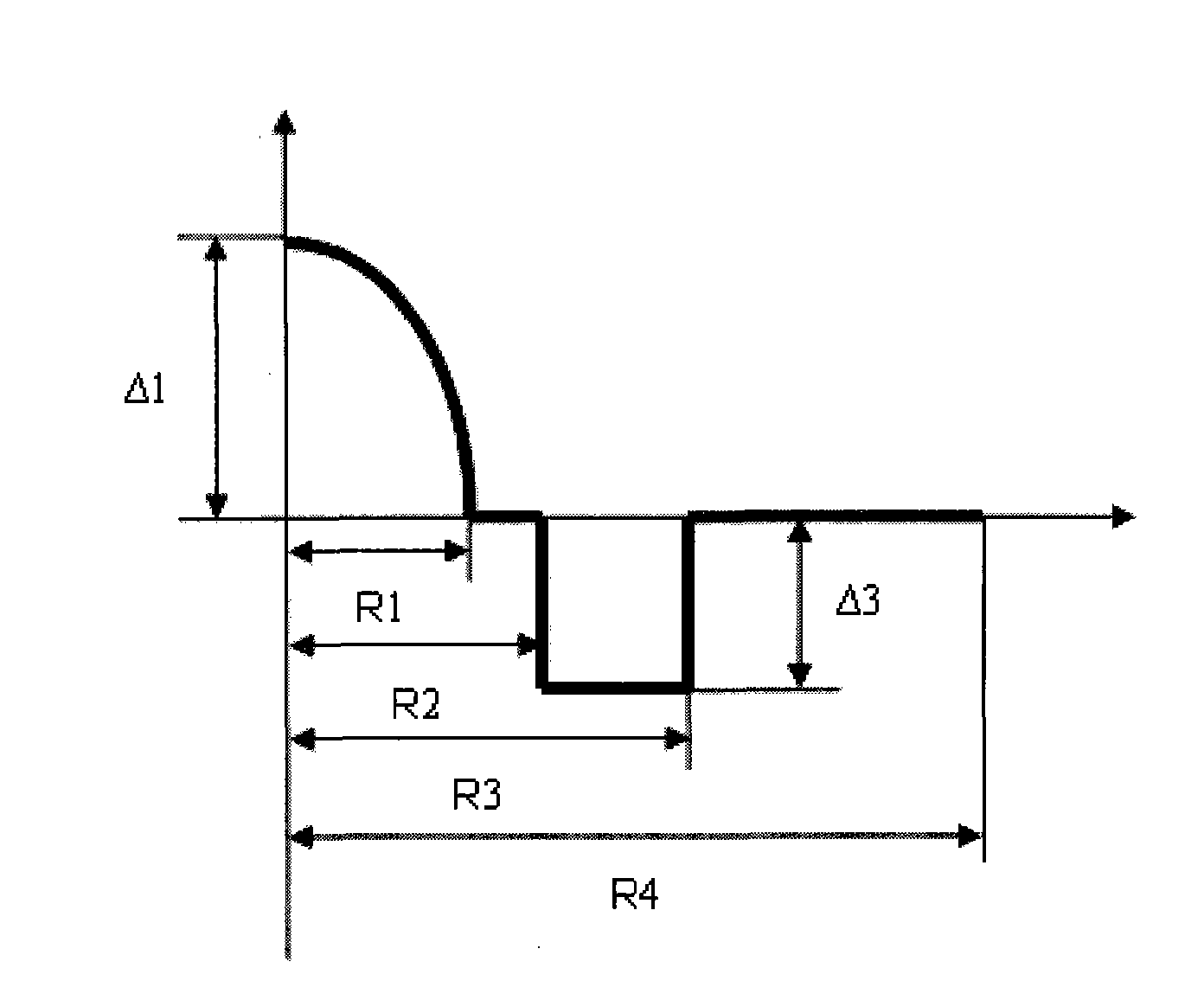
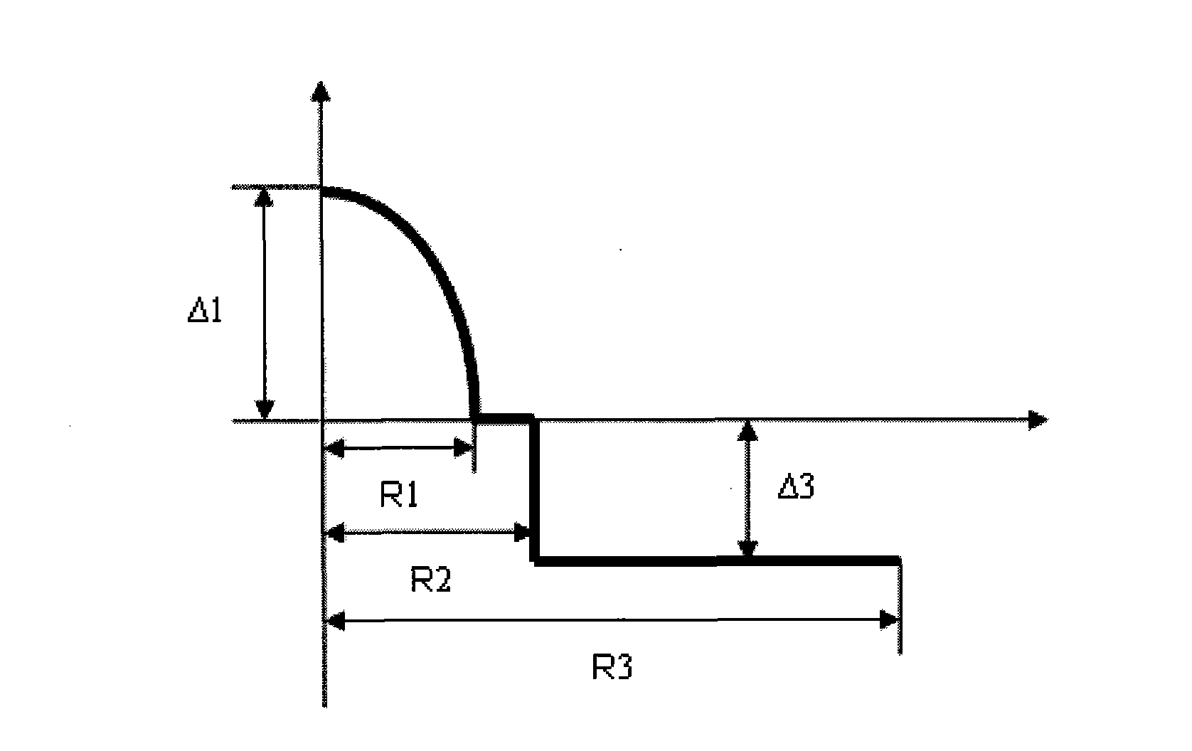
[0062] Some refractive index profiles were fabricated by PCVD process such as figure 1 Fiber samples are shown, and a n d test. The test process and fiber test results are as follows:

[0063] The pure quartz glass liner was fixed on a plasma-enhanced chemical vapor deposition (PCVD) lathe for dopant deposition, and the reaction gas silicon tetrachloride (SiCl 4 ) and oxygen (O 2 ), the reaction gas in the liner is ionized by microwaves into plasma, and finall...


PUM


Abstract

The invention relates to an anti-bending multimode fiber and manufacturing method thereof. The fiber comprises a core and a cladding and is characterized in that the radius of core R1 is 24-26 microns, refractive index section of the core is like a parabola, refractivity maximum delta1 is 0.9-1.1%, the cladding outside the core is composed of three parts, the radius of inner cladding R2 is 1.04-1.6 times of the radius of core R1, delta2 is minus 0.01-0.01%, intermediate cladding is gradually changed in refractive index, the radius of intermediate cladding R3 is 1.06-1.8 times of R1, refractivity is gradually changed into delta4 from delta2, the radius of outer cladding R4 is 2.38-2.63 times of R1, and delta4 is minus 0.20% to minus 0.40%. The invention reduces fiber bending additional attenuation and improves anti-bending performance of fiber but also basically eliminates inner stress of fiber, greatly improves mechanical properties of fiber, and service life of fiber operating in minor radius for a long time also can be guaranteed. The manufacturing method of the invention is simple, convenient and effective and is applicable to mass production.

Description

technical field [0001] The invention relates to a multimode optical fiber used in access networks or miniaturized optical devices and a manufacturing method thereof. The optical fiber has excellent bending resistance and belongs to the technical field of optical communication. Background technique [0002] Multimode optical fiber, especially high-bandwidth multimode optical fiber (such as OM3), has been widely used in short- and medium-distance optical fiber network systems (such as data centers and campus networks, etc.) due to relatively low system construction costs. For wiring indoors and in narrow environments, optical fibers are subjected to high bending stress, especially in applications where too long optical fibers are usually wound in increasingly miniaturized storage boxes, and optical fibers will withstand large bending stress. Therefore, it is necessary to design and develop multimode optical fibers with bending resistance to meet the requirements of indoor opti...

Claims


Application Information

Patent Timeline
Patent Type & Authority Applications(China)
IPC IPC(8): G02B6/036C03B37/018
CPCC03B2201/12G02B6/03638G02B6/0286G02B6/0365C03B37/01823G02B6/0288C03B2203/26C03B2201/31C03B2203/23C03B37/018G02B6/03633C03B37/01861
Inventor 张方海曹蓓蓓韩庆荣拉吉·马泰
Owner EVERPRO TECH COMPANY
Why Eureka
Try Eureka