Generator of engine

An engine and generator technology, applied in electromechanical devices, electrical components, electric components, etc., can solve the problems of high temperature engine oil temperature, wind resistance, poor ventilation and heat dissipation effect, etc., to achieve good ventilation and heat dissipation effect, flow direction rules are The effect of reasonable sequence and air duct structure

Inactive Publication Date: 2010-01-27
LONCIN MOTOR
View PDF0 Cites 11 Cited by
  • Summary
  • Abstract
  • Description
  • Claims
  • Application Information

AI Technical Summary

Problems solved by technology

Except for the partition plate between the hot and cold areas and the fan cover and shroud that come with the gasoline engine, there are no special parts for orderly guiding the wind in other parts of the shell, so the ventilation and heat dissipation effect is poor, especially when the inverter is installed. After the inverter, since it is necessary to ensure that all components of the inverter work at a suitable ambient temperature, there are higher requirements for ventilation and heat dissipation
[0003] The air-cooling process of the existing closed shell type frequency conversion gasoline engine generator is: the cold air entering from the louver vent on the side of the housing is first cooled to the frequency converter, but due to the large space around the frequency converter, the cold air passes through the frequency converter quickly and scattered , the inverter has not been sufficiently cooled; then the cold air is directed from the center of the motor rotor to the flywheel fan of the engine, because the motor rotor will cause certain resistance to the wind when it is running, and the stator end of the motor is directly connected with the flywheel fan cover, resulting in a large number of Wind cannot be channeled smoothly through the flywheel fan guard into the hot zone to cool the crankcase housing
These winds linger in the cold area, hindering the smooth intake of air from the air inlet and the smooth exhaust of the air outlet, making the temperature of the inductor of the entire gasoline generator inverter and the temperature of the engine oil higher, affecting the normal performance of the machine

Method used


Image

  • Generator of engine
  • Generator of engine
  • Generator of engine

Examples


Embodiment Construction

[0023] Below in conjunction with accompanying drawing and embodiment the present invention will be further described:

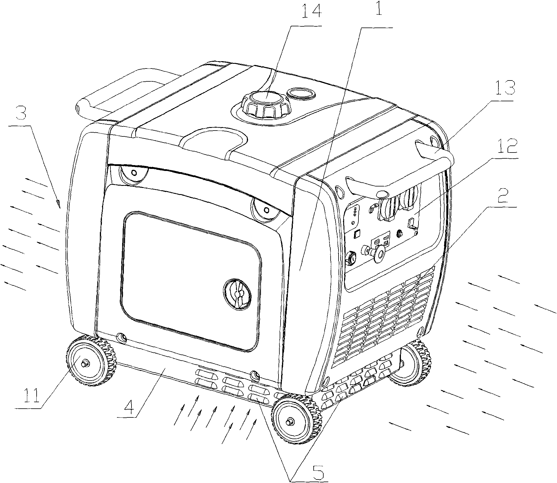
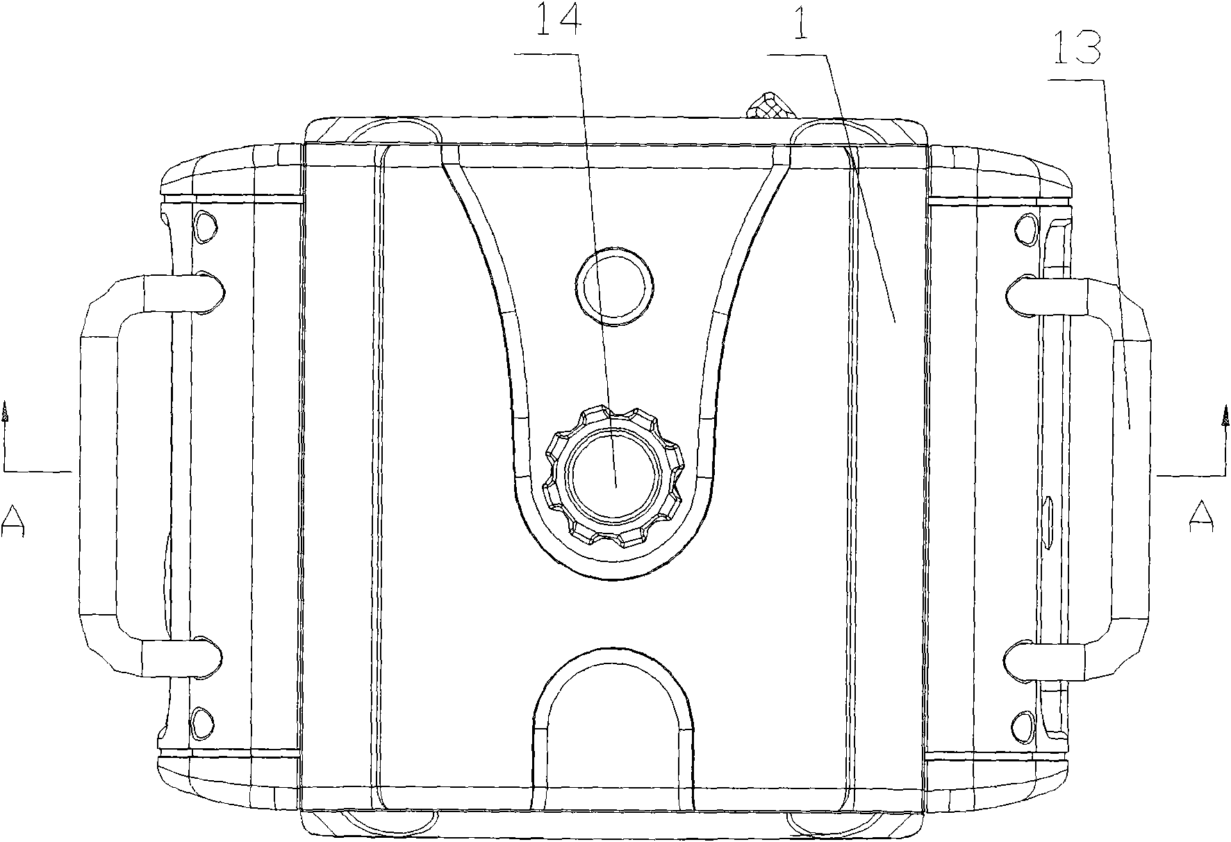
[0024] like figure 1 , figure 2 As shown, the gasoline engine generator in the embodiment of the present invention adopts a closed casing 1, wherein two opposite sides of the casing 1 are respectively provided with a louvered air inlet 2 and an air outlet 3, and the side plates of the frame 4 are also provided with Ventilation port 5 of louver type is arranged, and wheel 11 is equipped with at four corners of frame 4 bottoms, and the side of shell 1 is provided with control panel 12, and label 13 is handle pipe, and 14 is fuel cap.

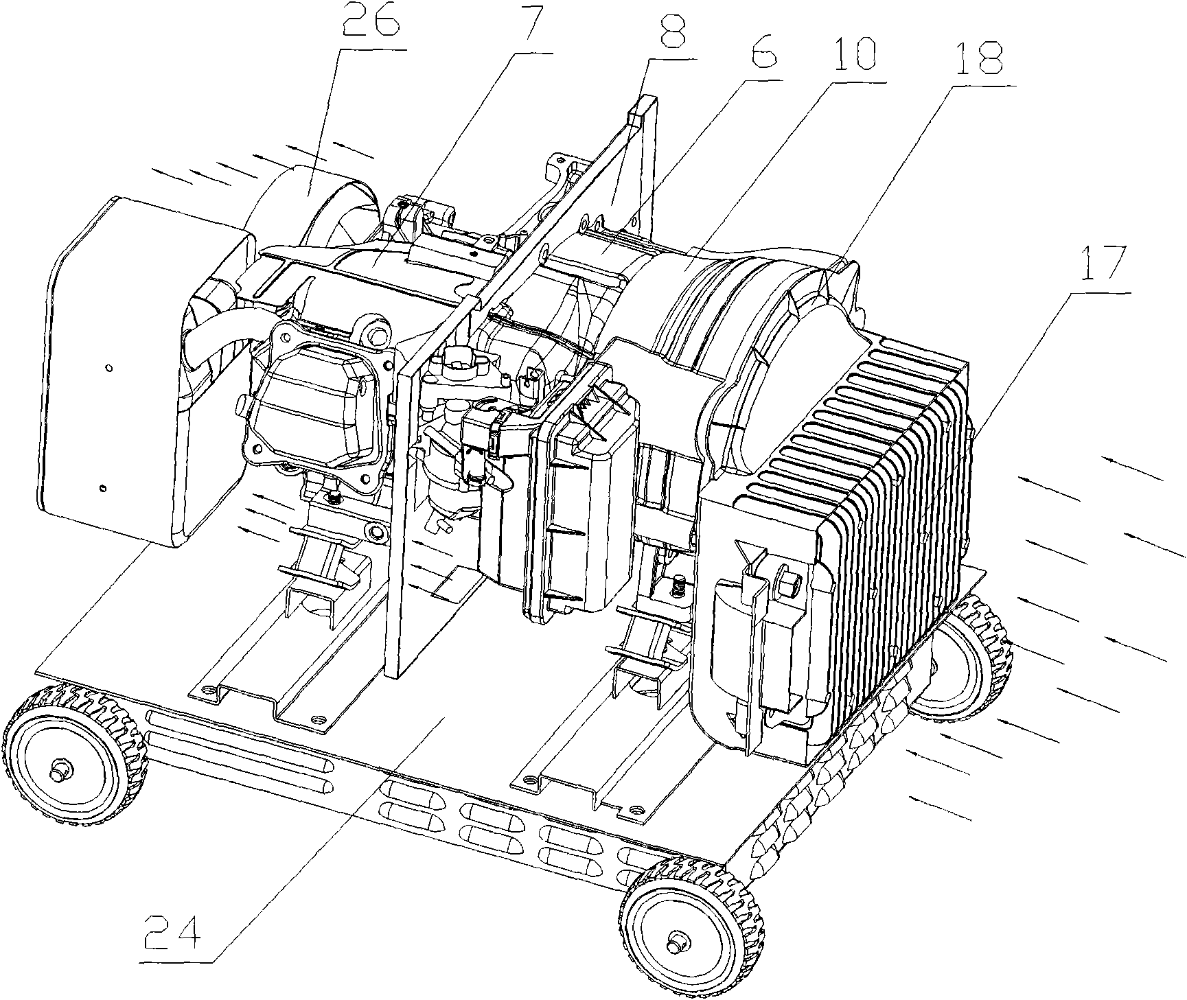
[0025] like image 3 , Figure 4 As shown, the engine is equipped with a fan cover 6 and an air guide cover 7, the fan cover 6 and the air guide cover 7 are respectively located on both sides of the hot and cold zone partition plate 8, the fan cover 6 covers the engine flywheel and the fan, and the air guide Cover 7 is posit...


PUM


Abstract

The invention provides a generator of a gasoline engine. A generating set is mounted on a stand and is arranged in a closed outer shell. Two opposite sides of the outer shell are respectively provided with an air inlet and an air outlet; an engine is provided with a fan sleeve (6) and an air-guiding sleeve (7) which are respectively arranged at both sides of a cold-hot area separator (8); a motor stator is covered by another air-guiding sleeve (10); a gap is formed between the end surface of the fan sleeve (6) and an engine stator (9); and one end of the air-guiding sleeve (10) is connected with the fan sleeve (6). By the technical scheme of the invention, an air duct structure in the generator becomes more reasonable, an air flow direction becomes more regular and orderly and various heating parts in the generator are cooled well. The gasoline engine generator running at a room temperature can control the temperature of a transducer inductor to be lower than 60 DEG C and the oil temperature of the generator to be lower than 125 DEG C so that favorable ventilation and radiation effects are obtained.

Description

technical field [0001] The invention relates to the technical field of engine generators, in particular to the improved design of the cooling air duct structure of gasoline engine generators. Background technique [0002] In order to look good and reduce noise, some gasoline engine generators adopt a closed shell structure, and only the bottom and two sides of the shell are provided with louvered ventilation openings. Except for the partition plate between the hot and cold areas and the fan cover and shroud that come with the gasoline engine, there are no special parts for orderly guiding the wind in other parts of the shell, so the ventilation and heat dissipation effect is poor, especially when the inverter is installed. After the inverter, since it is necessary to ensure that all components of the inverter work at a suitable ambient temperature, there are higher requirements for ventilation and heat dissipation. [0003] The air-cooling process of the existing closed she...

Claims


Application Information

Patent Timeline
Patent Type & Authority Applications(China)
IPC IPC(8): H02K9/02
Inventor 隆郁田辉范海峰袁磊刘明治王小勇
Owner LONCIN MOTOR
Why Eureka
Try Eureka