
Thermoelectric energy generator and quick energy storage system thereof

An energy storage system and generator technology, applied in the field of energy storage systems, can solve the problems of reduced temperature difference between hot and cold ends of thermoelectric chips, slow heat dissipation, unfavorable installation and space utilization, etc. Effectiveness of utilization rate and improvement of thermoelectric conversion efficiency

Inactive Publication Date: 2010-02-03
王钦戊
View PDF5 Cites 3 Cited by
  • Summary
  • Abstract
  • Description
  • Claims
  • Application Information

AI Technical Summary

Problems solved by technology

As for the method of U.S. Patent No. 7180264 and Chinese Patent No. 200580019773.3, which makes the cold end heat of the thermoelectric chip dissipate directly into the air, the thermoelectric conversion efficiency is not good because of the slow heat dissipation.
[0012] Although the thermoelectric chips of other patents have improved the heat dissipation efficiency of the cold end through fans or cooling fins, these patents use the design that the hot end of the thermoelectric chip is directly in contact with the heat source or conducts heat through the heat conduction plate, so that the heat of the thermoelectric chip The terminal cannot effectively and reliably keep the heat energy, thereby reducing the temperature difference between the hot and cold ends of the thermoelectric chip, and thus the thermoelectric conversion efficiency of the thermoelectric chip is still unsatisfactory; in addition, both the fan and the cooling fin have a large volume, so Not conducive to installation and space utilization

Method used


Image

  • Thermoelectric energy generator and quick energy storage system thereof
  • Thermoelectric energy generator and quick energy storage system thereof
  • Thermoelectric energy generator and quick energy storage system thereof

Examples


Embodiment Construction

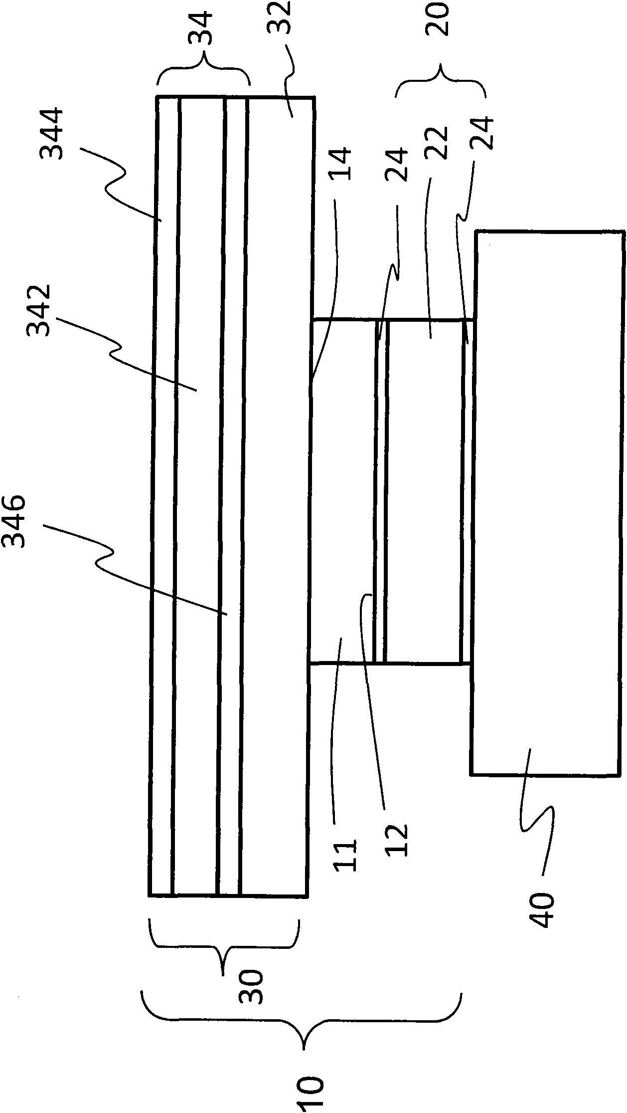
[0035] see figure 1 , a thermoelectric energy generator 10 uses a thermoelectric chip 11 for thermoelectric conversion. The thermoelectric chip 11 has a hot end 12 and a cold end 14 , and the hot end 12 and the cold end 14 are respectively located on opposite sides. The thermoelectric chip 11 is composed of multiple sets of N-type thermoelectric materials and P-type thermoelectric materials.

[0036] A heat sink 20 is bonded to the hot end 12 of the thermoelectric chip 11 . Furthermore, the heat-absorbing sheet 20 is a metal sheet 22 with a heat-retaining material 24 on its surface. The metal sheet 22 is thin copper or aluminum sheet; the thermal insulation material 24 is black photoresist or carbon black.

[0037] One side of the heat absorbing sheet 20 is pasted on a heat source 40 for absorbing heat, and the heat is kept on the hot end 12 of the thermoelectric chip 11 by the effect of the thermal insulation material 24, so the hot end 12 can be kept at a high temperature...


PUM


Abstract

The invention discloses a thermoelectric energy generator and a quick energy storage system thereof. The thermoelectric energy generator consists of a thermoelectric wafer, a heat absorbing plate anda radiating fin, wherein the heat absorbing plate is arranged at a hot end of the thermoelectric wafer and used for retaining the heat of a heat source as much as possible so that the hot end of the thermoelectric wafer can be retained in a high temperature state; and the radiating fin is arranged at a cold end of the thermoelectric wafer and used for radiating the heat at the cold end of the thermoelectric wafer. Therefore, the hot end and the cold end of the thermoelectric wafer have large temperature difference so as to improve the thermoelectric conversion efficiency. The thermoelectric energy generator is connected with a quick energy storage interface with a super-capacitance architecture, and the quick energy storage interface can be quickly charged and discharged to another energystorage device so as to form the quick energy storage system and achieve the effect of quickly storing micro power.

Description

technical field [0001] The invention relates to an energy generator and an energy storage system, in particular to a thermoelectric energy generator that uses a thermoelectric conversion chip to convert thermal energy into electrical energy, and an energy storage system that can further quickly store the electrical energy generated by the energy generator . Background technique [0002] The basic working principle of thermoelectric energy conversion of thermoelectric chip can be explained by the phenomenon of thermopile junction formed by a single group of N-type thermoelectric materials and P-type thermoelectric materials. The resulting temperature difference makes the main conduction carriers (P-type holes, N-type electrons) in the thermoelectric material diffuse from the high-temperature hot end to the low-temperature cold end, resulting in a PN junction thermopile at the cold end. The accumulation of positive and negative charges (positive charges are accumulated at the...

Claims


Application Information

Patent Timeline
Patent Type & Authority Applications(China)
IPC IPC(8): H01L35/30H02N11/00H10N10/13
Inventor 王钦戊
Owner 王钦戊
Learn More