
Ring thermoelectric device

A thermoelectric device and thermoelectric element technology, applied in the direction of thermoelectric device components, etc., can solve the problems such as insufficient utilization of medium-temperature or high-temperature heat source resources, low power generation efficiency, damage to annular thermoelectric elements, etc., to improve power generation efficiency and output power density, Improve the service life and improve the effect of the temperature difference between the cold and hot ends

Active Publication Date: 2019-02-26
SHANGHAI INST OF CERAMIC CHEM & TECH CHINESE ACAD OF SCI
View PDF10 Cites 0 Cited by
  • Summary
  • Abstract
  • Description
  • Claims
  • Application Information

AI Technical Summary

Problems solved by technology

First of all, ring-shaped thermoelectric devices using a single thermoelectric material cannot make full use of medium-temperature or high-temperature heat source resources, and the power generation efficiency is low; secondly, in order to ensure that the ring-shaped thermoelectric device does not deform during use, it is necessary to use ceramic tubes with a certain thickness and strength on the inner and outer surfaces (considering corrosion resistance and electrical insulation) to fix
The ring-shaped thermoelectric device is fixed by the inner and outer ceramic tubes, and the thermal stress cannot be released when used in a large temperature difference environment, which will cause damage to the ring-shaped thermoelectric device

Method used


Image

  • Ring thermoelectric device
  • Ring thermoelectric device
  • Ring thermoelectric device

Examples


Embodiment 1

[0062] In this embodiment, ring-shaped thermoelectric elements and thermoelectric devices composed of segments are designed according to the properties of skutterudite materials and bismuth telluride materials. The operating temperature of the annular device is from the hot end to 770K, and from the cold end to 320K.

[0063]The skutterudite material used is Yb 0.3 co 4 Sb 12 (n-type) and Ce 0.9 Fe 4 Sb 12 (p-type), the bismuth telluride material used is (Bi 2 Te 3 ) 0.90 (Sb 2 Te 3 ) 0.05 (Sb 2 Se 3 ) 0.05 (n-type) and (Bi 2 Te 3 ) 0.25 (Sb 2 Te 3 ) 0.72 (Sb 2 Se 3 ) 0.03 (p-type).

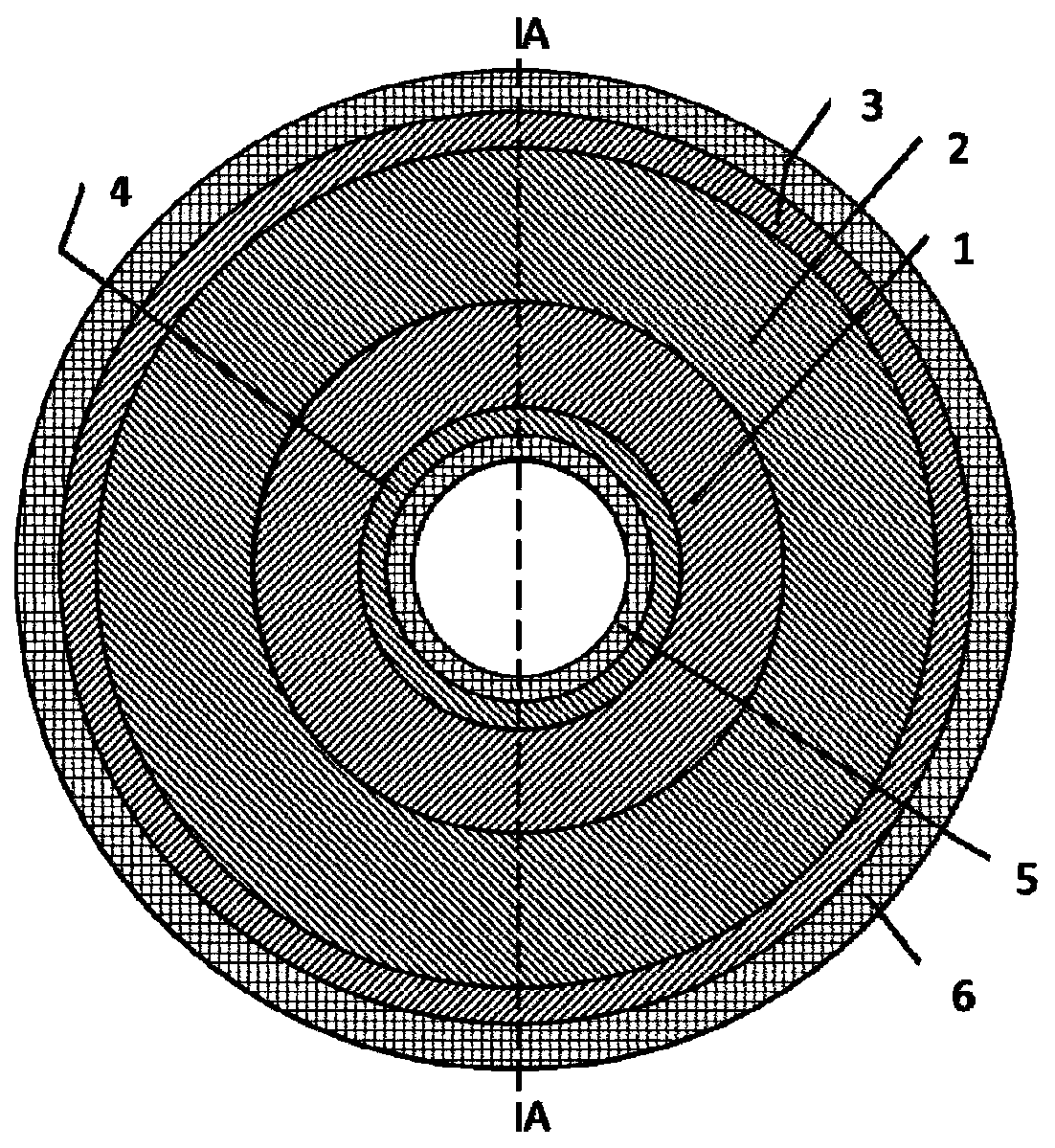
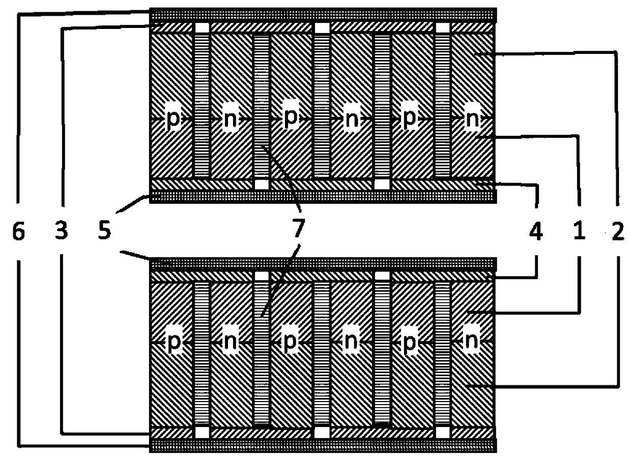
[0064] The structure of the ring element is figure 1 . The outer annulus of the annular segmented device is the hot end, and the inner annulus is the cold end. The specific implementation is that the skutterudite material part is the outer ring material part, and the bismuth telluride material part is the inner ring material part.

[0065] The inner diameter of the sku...

Embodiment 2

[0070] In this embodiment, ring-shaped thermoelectric elements and thermoelectric devices composed of segments are designed according to the properties of lead telluride materials and bismuth telluride materials. The operating temperature of the ring device is 670K at the hot end and 320K at the cold end.

[0071] The lead telluride material used is Ag 0.86 Pb 19+x SbT 20 (n-type) and Ag 0.9 Pb 9 sn 9 Sb 0.6 Te 20 (p-type), the bismuth telluride material used is (Bi 2 Te 3 ) 0.90 (Sb 2 Te 3 ) 0.05 (Sb 2 Se 3 ) 0.05 (n-type) and (Bi 2 Te 3 ) 0.25 (Sb 2 Te 3 ) 0.72 (Sb 2 Se 3 ) 0.03 (p-type).

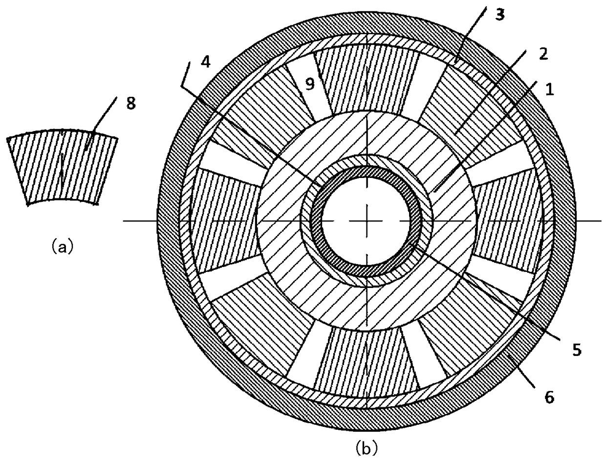
[0072] The structure of the ring element is Figure 7 , lead telluride and bismuth telluride material parts are evenly divided into 8 small parts. The outer annulus of the annular segmented device is the hot end, and the inner annulus is the cold end. Specifically, the lead telluride material part is an outer ring material part, and the bismuth telluride materi...


PUM


Abstract

The annular thermoelectric device of the present invention is provided with: a plurality of annular P-type thermoelectric elements and N-type thermoelectric elements arranged alternately along the axial direction; annular isolation provided between each of the P-type thermoelectric elements and N-type thermoelectric elements. layer; connect the outer ring conduction electrodes of each pair of P-type thermoelectric elements and N-type thermoelectric elements on the outer wall; connect adjacent pairs of the N-type thermoelectric elements on the inner wall in a staggered manner with the outer ring conduction electrodes. Thermoelectric elements and inner ring current-guiding electrodes of P-type thermoelectric elements; and tubular components respectively located on the inner and outer peripheral sides of the annular thermoelectric device; each thermoelectric element includes at least two annular thermoelectric materials arranged radially outward in sequence. part.

Description

technical field [0001] The invention belongs to the technical field of thermoelectric conversion, and in particular relates to an annular thermoelectric device. Background technique [0002] As an environmentally friendly renewable energy technology, thermoelectric conversion technology has attracted widespread attention in the world in recent years. Thermoelectric power generation technology is a new technology that uses the Seebeck effect of semiconductor materials to directly convert temperature differences into electrical energy. This technology has the advantages of high reliability, no pollution and no noise, and it will have a good application prospect in high-tech fields such as the recovery and utilization of industrial waste heat and automobile exhaust waste heat, as well as military power supplies. [0003] A thermoelectric device is often composed of multiple n-type and p-type semiconductor thermoelectric elements. Since the output voltage of each thermoelectri...

Claims


Application Information

Patent Timeline
Patent Type & Authority Patents(China)
IPC IPC(8): H01L35/02H10N10/80
Inventor 黄向阳顾明仇鹏飞柏胜强唐云山廖锦城陈立东
Owner SHANGHAI INST OF CERAMIC CHEM & TECH CHINESE ACAD OF SCI
Learn More