Anaerobic biochemical reactor
A biochemical reactor and sub-chamber technology, applied in anaerobic digestion treatment and other directions, can solve the problems of large hydraulic elevation loss, high control requirements, sensitive sewage impact reaction, etc., and achieve high hydraulic loss, small reaction efficiency, and market application prospects. considerable effect
- Summary
- Abstract
- Description
- Claims
- Application Information
AI Technical Summary
Problems solved by technology
Method used
Image

Examples
Embodiment 1
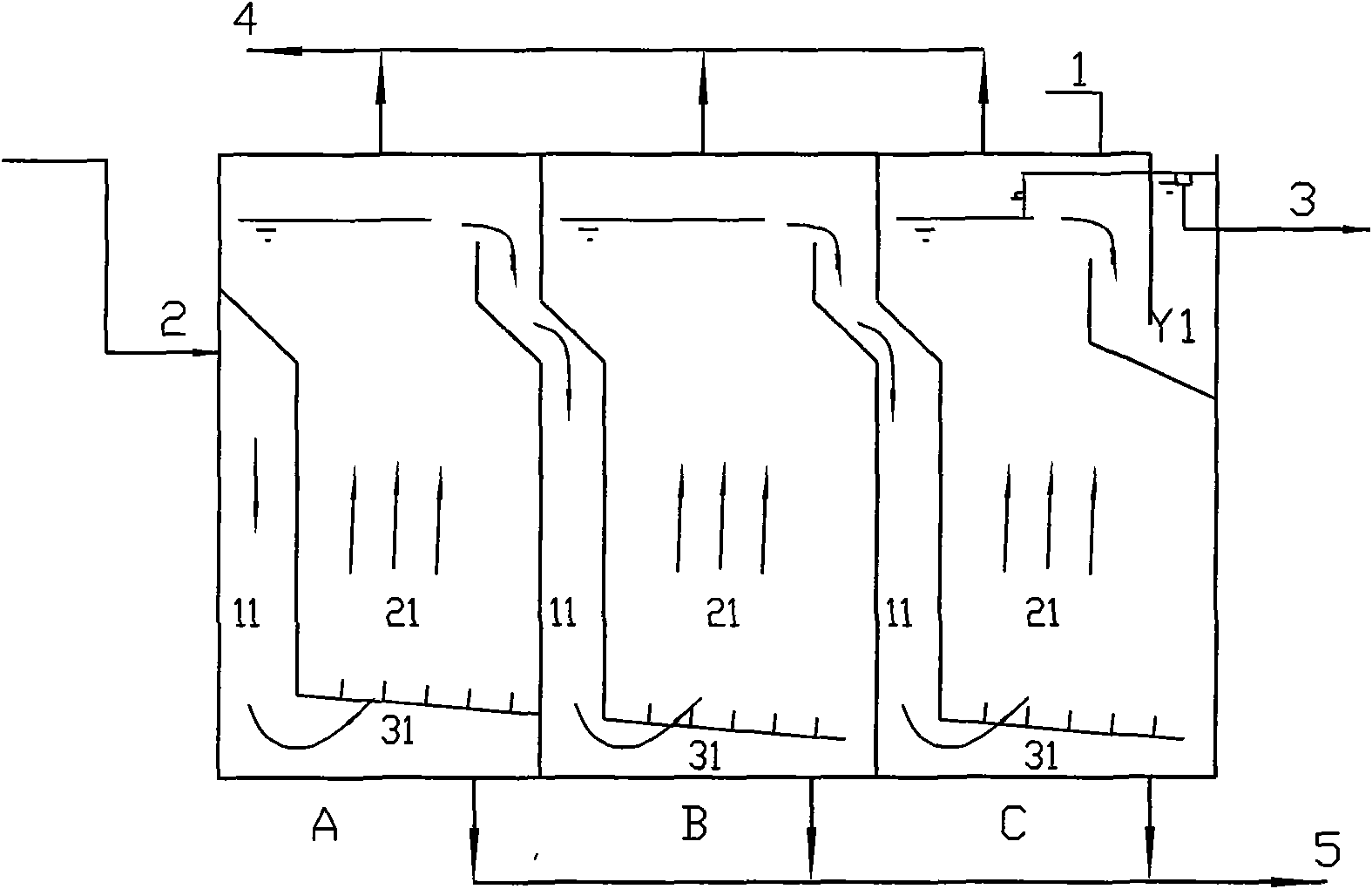
[0018] Such as figure 1 Shown as figure 1 It is a schematic diagram of the low-load application of the present invention.
[0019] It is suitable for low COD load such as 5kg / m3.d or less. Its operating conditions are like UASB, but the difference is: horizontal multi-stage series structure, no gas-water separator is required, a sedimentation tank can be set at the last stage to keep sludge.
[0020] The anaerobic biochemical reactor has a rectangular tank body 1, and the depth of the tank body 1 can be between 5-12m. The tank body 1 can be divided into A, B, C...Y and other multi-stage compartments. Each sub-chamber A, B, C, ... Y is composed of a downward flow passage 11 and an upward flow passage 21.
[0021] The multi-stage compartments are in series structure, and each stage has a specific reaction phase, namely biological and matrix, with high reaction efficiency; the series structure can increase the impact resistance and provide reaction control time;
[0022] When working, t...
Embodiment 2
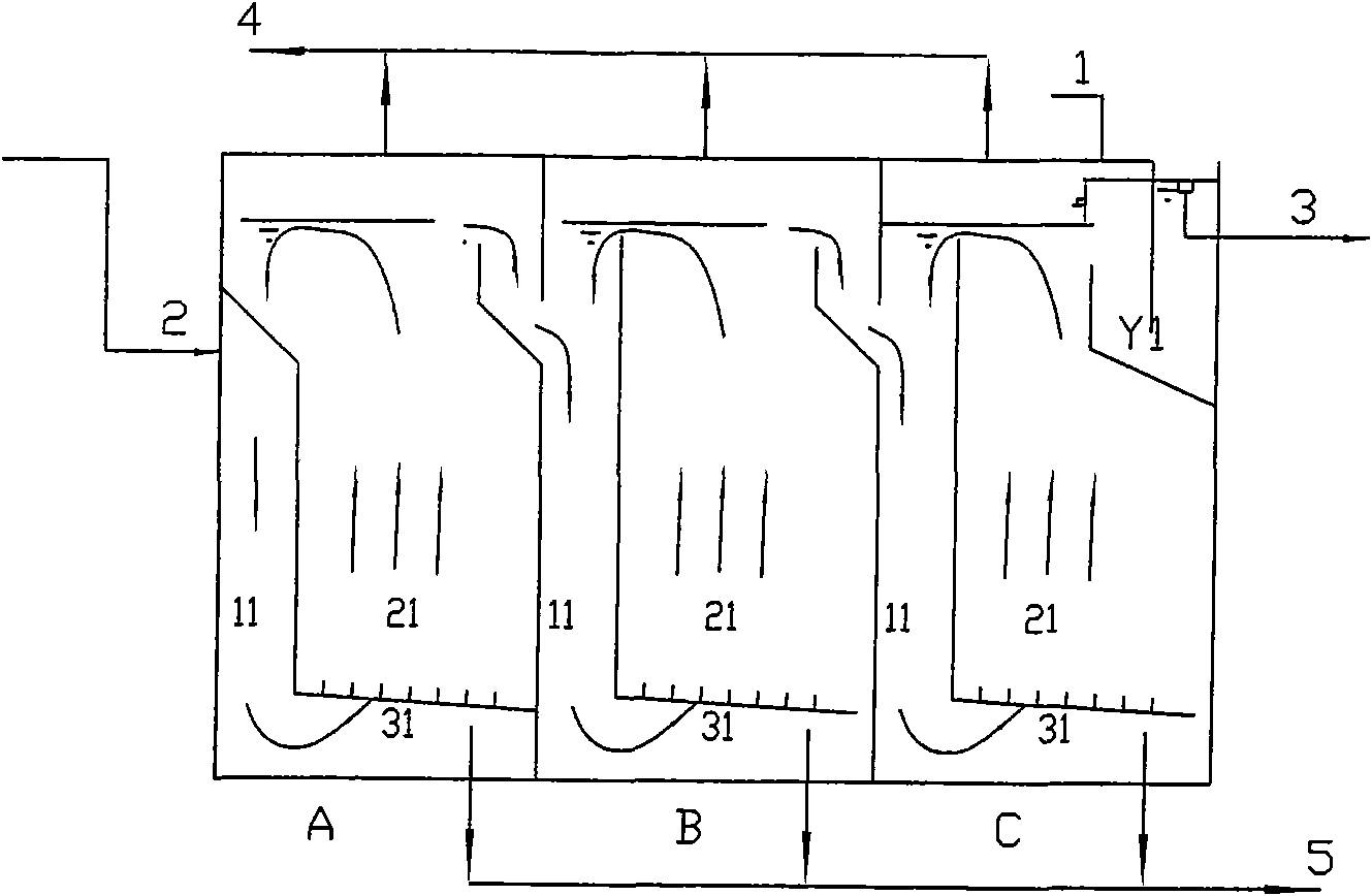
[0025] Such as figure 2 As shown, Figure 2 is a schematic structural diagram of a high-load application in an embodiment of the present invention.
[0026] It is suitable for the situation where the COD load is higher than 5kg / m3.d. Its operating conditions are like IC. The difference is: each sub-chamber is a horizontal multi-stage series structure, no gas-water separator is required, and a sedimentation tank is set in the last sub-chamber to keep sludge.
[0027] The sewage enters the downward flow passage 11 of the first sub-chamber A from the water inlet pipe 2, and is distributed by the lower water distribution system 31 and then transferred to the upward flow passage 21, where it comes into contact with the suspended or expanded anaerobic sludge bed that has been formed. Oxygen biochemical reaction and biogas production. After the gas and liquid are naturally separated at the free liquid surface, the sewage flows into the next sub-chamber B, sub-chamber C..., and is discharg...
Embodiment 3
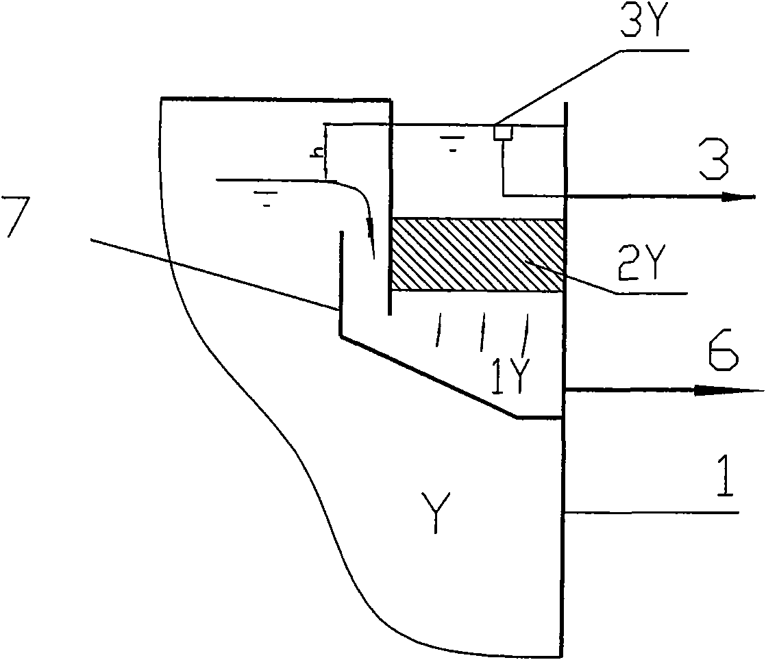
[0030] Such as image 3 As shown, image 3 It is a schematic diagram of the structure of the water outlet chamber in the anaerobic biochemical reactor of the present invention.
[0031] A sedimentation tank can be formed in the outlet chamber Y to precipitate suspended solids in the water, that is, biological sludge to ensure that the sludge is not lost. The sedimentation tank consists of a water outlet chamber Y and its inner water distribution area 1Y, a sedimentation area 2Y, and an outlet weir 3Y.
[0032] The structure is composed of a sedimentation tank 7 in the outlet chamber Y, an inlet distribution area 1Y in the lower part of the sedimentation tank 7, a sedimentation area 2Y in the middle, and an outlet weir 3Y in the upper part.
[0033] The sedimentation zone 2Y can be equipped with fillers such as inclined plates, etc., and the method is the same as the current general regulations.
[0034] Sewage enters the inlet water distribution area 1Y from the front stage, passes ...
PUM
 Abstract
Description
Claims
Application Information
 - R&D
- Intellectual Property
- Life Sciences
- Materials
- Tech Scout
- Unparalleled Data Quality
- Higher Quality Content
- 60% Fewer Hallucinations
Browse by: Latest US Patents, China's latest patents, Technical Efficacy Thesaurus, Application Domain, Technology Topic, Popular Technical Reports.
© 2025 PatSnap. All rights reserved.Legal|Privacy policy|Modern Slavery Act Transparency Statement|Sitemap|About US| Contact US: help@patsnap.com