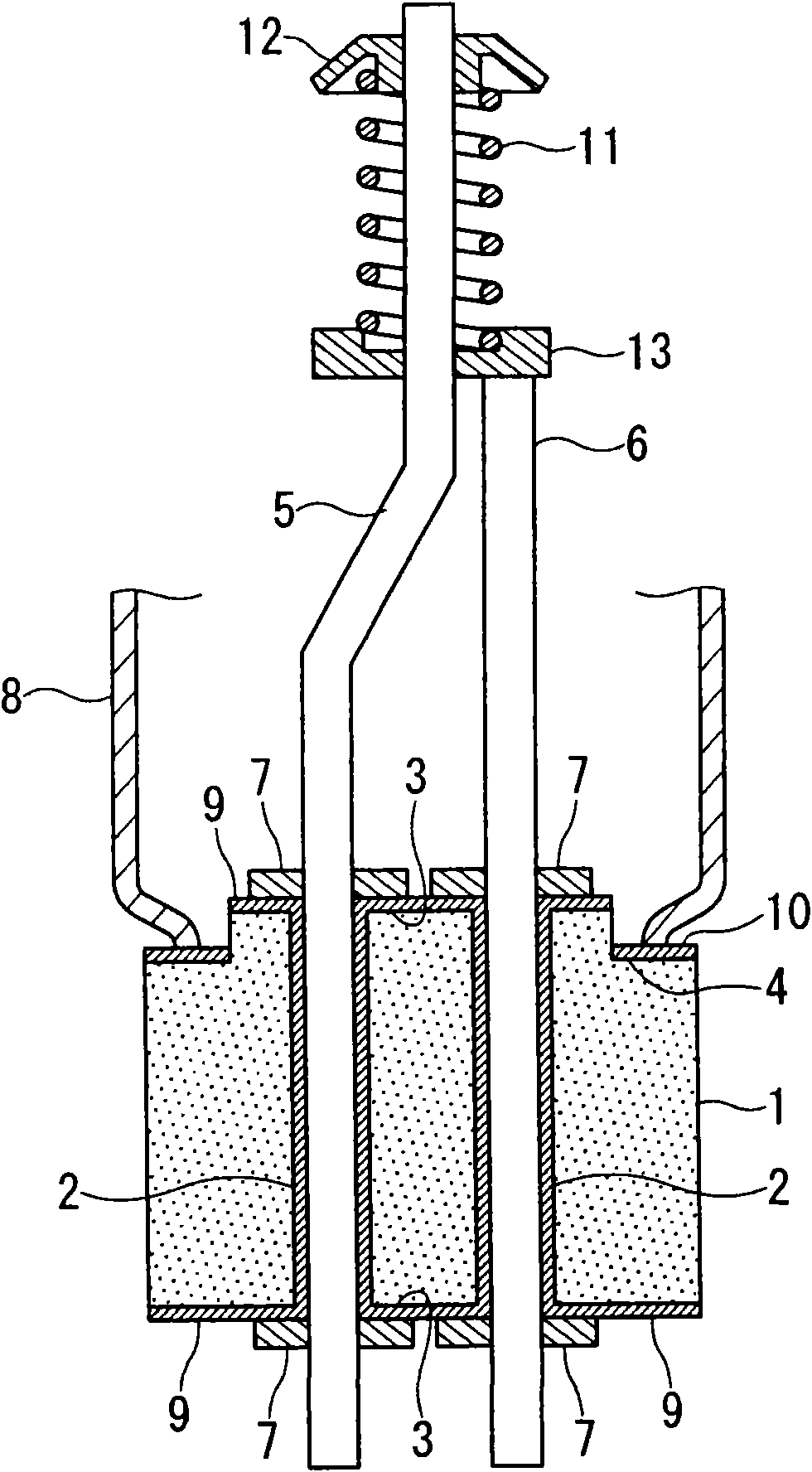
Ceramic part for magnetron, magnetron employing the same, and process for producing ceramic part for magnetron
A manufacturing method and ceramic technology, applied in the manufacture of discharge tubes/lamps, magnetrons, shells/containers of time-of-flight electron tubes, etc., can solve the problem that the yield rate has not been sufficiently improved, and the yield rate has not been fully obtained. Improvement, complexity and other problems, to achieve the effect of improving yield, improving reliability, and improving joint strength
- Summary
- Abstract
- Description
- Claims
- Application Information
AI Technical Summary
Problems solved by technology
Method used
Image
Examples
preparation example Construction
[0052] The preparation of the Mo-Mn paste is preferably carried out as follows: the Mo powder with an average particle diameter of 0.5 to 10 μm and the Mn powder with an average particle diameter of 0.5 to 10 μm are respectively pulverized for more than 40 hours, and then mixed with Adhesives are mixed. The ratio of Mo and Mn in the Mo—Mn-based paste is 4 to 12 mass %, preferably 6 to 8 mass %, when the total of Mo and Mn is 100 mass %. A series of steps for adjusting the Mo—Mn-based paste is preferably performed under an inert atmosphere such as nitrogen gas. In particular, since Mn is an active metal, it is preferable to perform the treatment in an inert atmosphere.
[0053] Generally, when forming a Mo—Mn metallization layer, voids are easily formed in the metallization layer. The voids are mainly gaps formed when the organic binder is burned, and if the particle diameters of the Mo powder and the Mn powder are large, the gaps are likely to become large. Therefore, in or...
Embodiment 1、 comparative example 1~3
[0096] [Example 1, Comparative Examples 1 to 3, Reference Example 1]
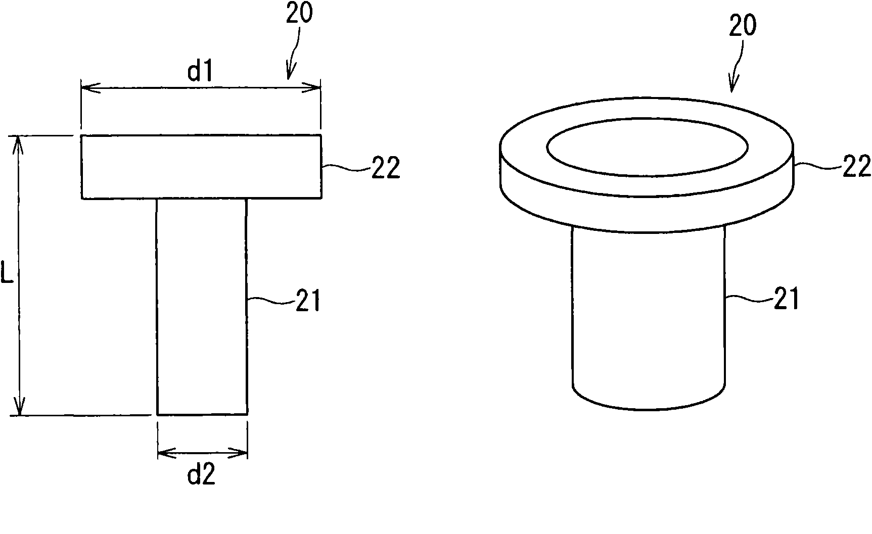
[0097] Example 1, Comparative Examples 1 to 3, and Reference Example 1 manufactured a rod-shaped article for a magnetron by the following steps.
[0098] Example 1: Process A1 → Process B1 → Process C1 → Process D1 → Process E1 → Process F1
reference example 1
[0102] Reference example 1: Process A1→Process B1→Process C1→Process D1→Process E1→Process F2
[0103] Each process is as follows.
[0104] Step A1: Use the following alumina sintered body in which Mn oxide (MnO 2 ), silicon oxide and magnesium oxide as sintering aids for firing. The Mn content in the alumina sintered body was 3.0 wt % in terms of Mn as a simple substance, 1.9 wt % in terms of Si as a simple substance, and 2.4 wt % in terms of Mg as a simple substance. In addition, when the composition of the grain boundary phase in the alumina sintered body was analyzed by X-ray diffraction method, no crystal peak was detected, and it was found to be a glass phase.
[0105] Step A2: Prepare the same alumina sintered body as in Step A1 except that Mn is not contained.
[0106] Step B1: Mo powder with an average particle diameter of 2 μm and Mn powder with an average particle diameter of 2 μm were pulverized for 75 hours using a ball mill. After the Mo powder and the Mn pow...
PUM
 Abstract
Description
Claims
Application Information
 - R&D
- Intellectual Property
- Life Sciences
- Materials
- Tech Scout
- Unparalleled Data Quality
- Higher Quality Content
- 60% Fewer Hallucinations
Browse by: Latest US Patents, China's latest patents, Technical Efficacy Thesaurus, Application Domain, Technology Topic, Popular Technical Reports.
© 2025 PatSnap. All rights reserved.Legal|Privacy policy|Modern Slavery Act Transparency Statement|Sitemap|About US| Contact US: help@patsnap.com


