Nanofiber filtration material and forming method thereof

A nanofiber and filter material technology, applied in the field of nanofiber filter material, can solve the problems of low soft mechanical strength, high pressure loss, and fragility

Inactive Publication Date: 2010-02-24
IND TECH RES INST
View PDF0 Cites 43 Cited by
  • Summary
  • Abstract
  • Description
  • Claims
  • Application Information

AI Technical Summary

Problems solved by technology

[0003] Currently commercially available HEPA filter materials are mainly composed of glass fiber or polypropylene melt-blown non-woven fabric, the most common is glass fiber non-woven fabric filter material, which is relatively easy to break during folding processing; after electrostatic treatment, polypropylene melt-blown non-woven fabric, due to the material The softer mechanical strength is not high, a

Method used


Image

  • Nanofiber filtration material and forming method thereof
  • Nanofiber filtration material and forming method thereof
  • Nanofiber filtration material and forming method thereof

Examples


Embodiment 1

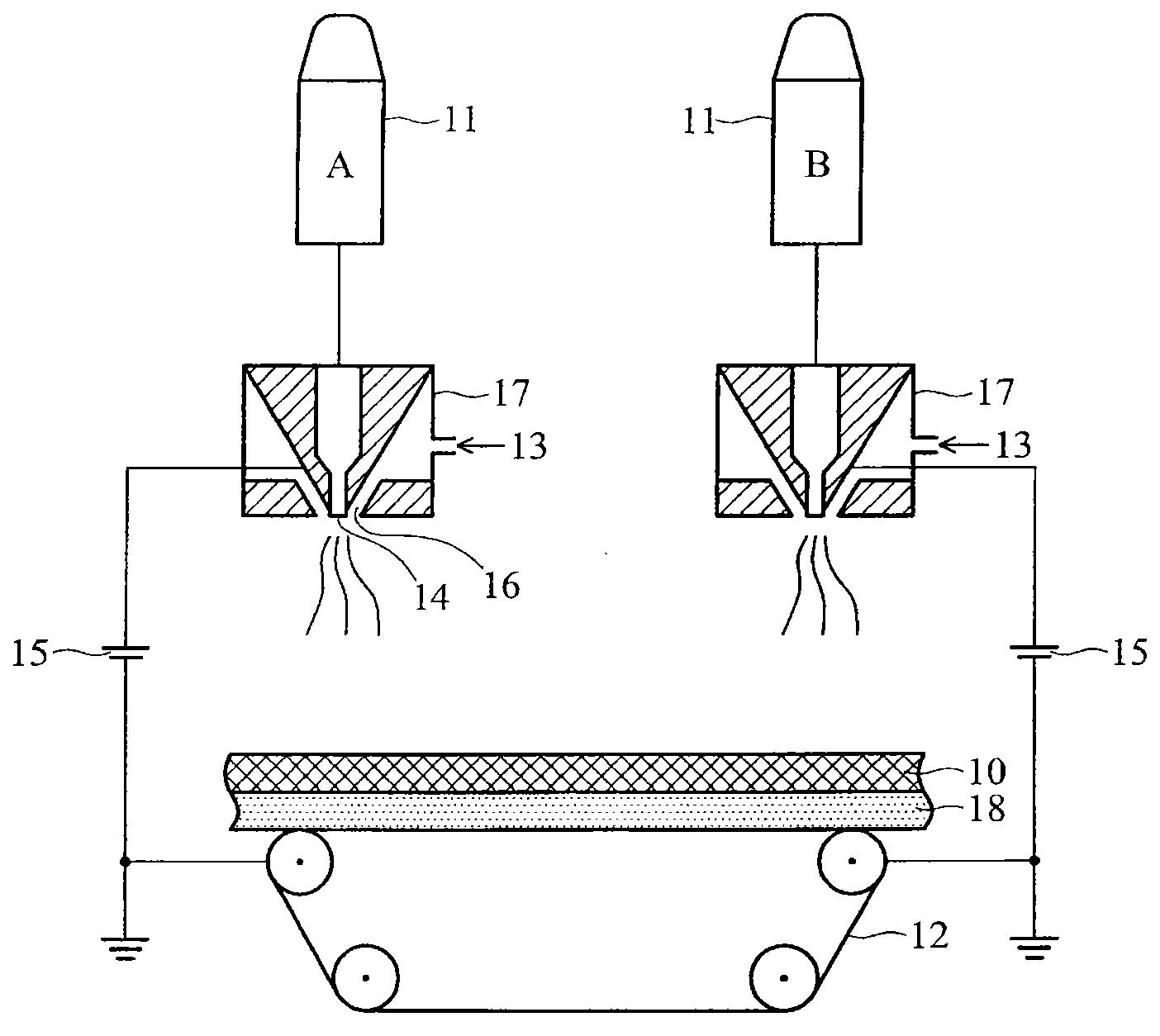
[0023] In this embodiment, the polymer solution is polycarbonate dissolved in a mixed solvent of tetrahydrofuran and dimethylethylamine, and the concentrations are 12% and 15% (by weight, the same below). The polymer solutions 12% and 15% are respectively interwoven in an electric field environment by electrospinning in a uniform interlaced manner to form two kinds of nanofiber diameter distributions and uniformly mixed to form a nanofiber layer cotton web and deposited on a grammage of 15g / m 2 Meltblown nonwoven cotton mesh substrate. The distance between the spinneret and the collecting cotton net base material is 20cm, the applied voltage is 40kV and the output speed of 25μL / min / hole, and there is gas-assisted stretching of the fiber at the spinneret at the same time, the polymer solution is 12% and 15% %The two concentrations are interwoven in the above-mentioned electric field environment in a uniform interlacing manner to form two kinds of nanofiber diameter distribution...

Embodiment 2

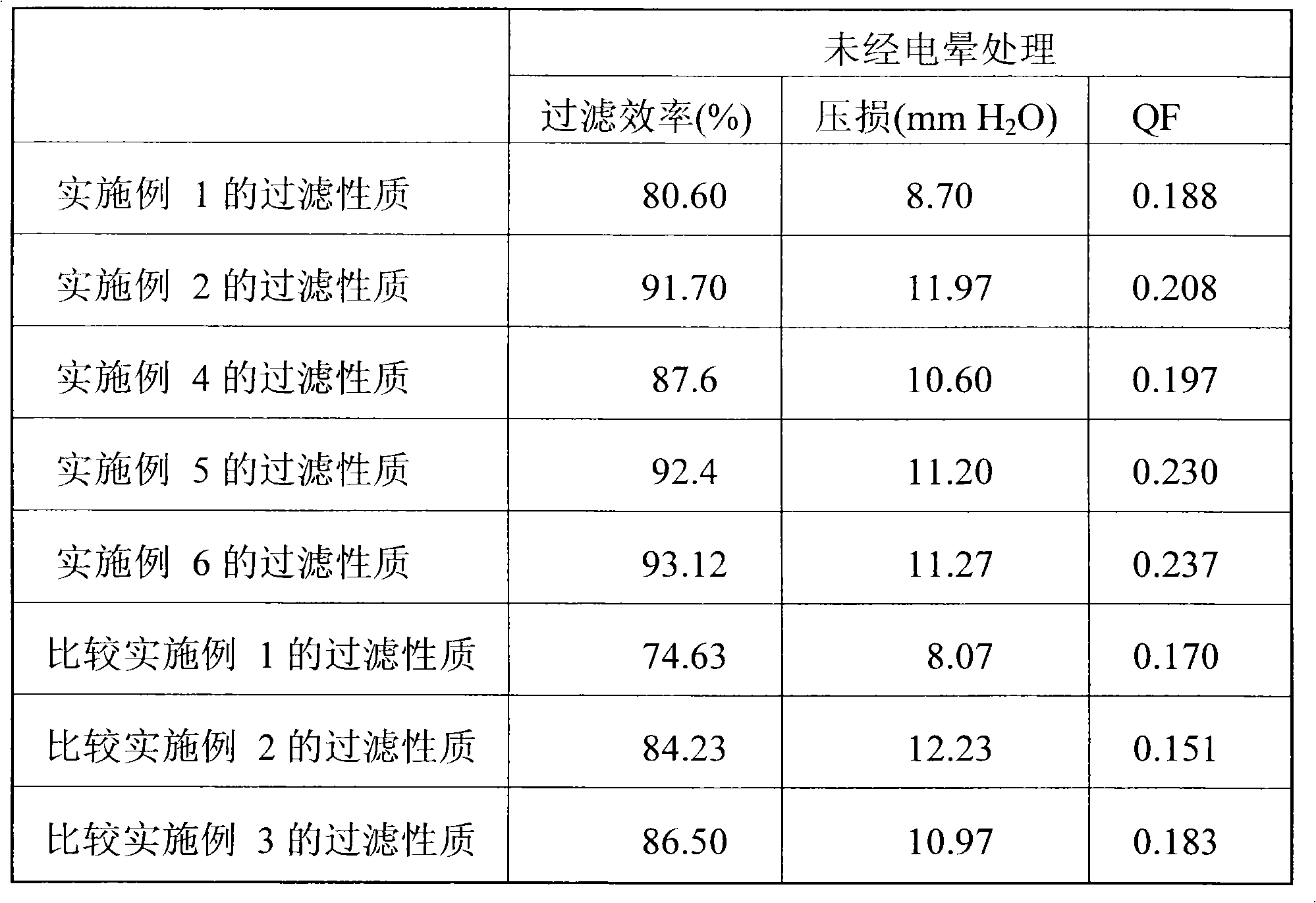
[0025] In this embodiment, the polymer solution is polycarbonate dissolved in a mixed solvent of tetrahydrofuran and dimethylethylamine, and the concentrations are 12%, 13.5%, and 15% respectively. Under the same electrospinning conditions and substrate as in Example 1, a nanofiber cotton web is formed, the difference is that the three concentrations of polymer solutions of 12%, 13.5%, and 15% are used to interweave in a uniform interlaced manner to form three A nanofiber layer cotton web with nanofiber diameter distribution and uniform mixing, the nanofiber layer gram weight is measured as 1.36g / m 2 , the thickness is 11 μm, and the average fiber diameter of the nanofiber cotton web formed by uniform mixing is 150nm±30nm. The nanofibrous layer formed by uniformly interlacing the three concentrations of polymer solutions of 12%, 13.5%, and 15% respectively, and the filtration properties of the 260nm particles measured by TSI 8130 at a gas flow rate of 14cm / s are shown in Table...

Embodiment 3

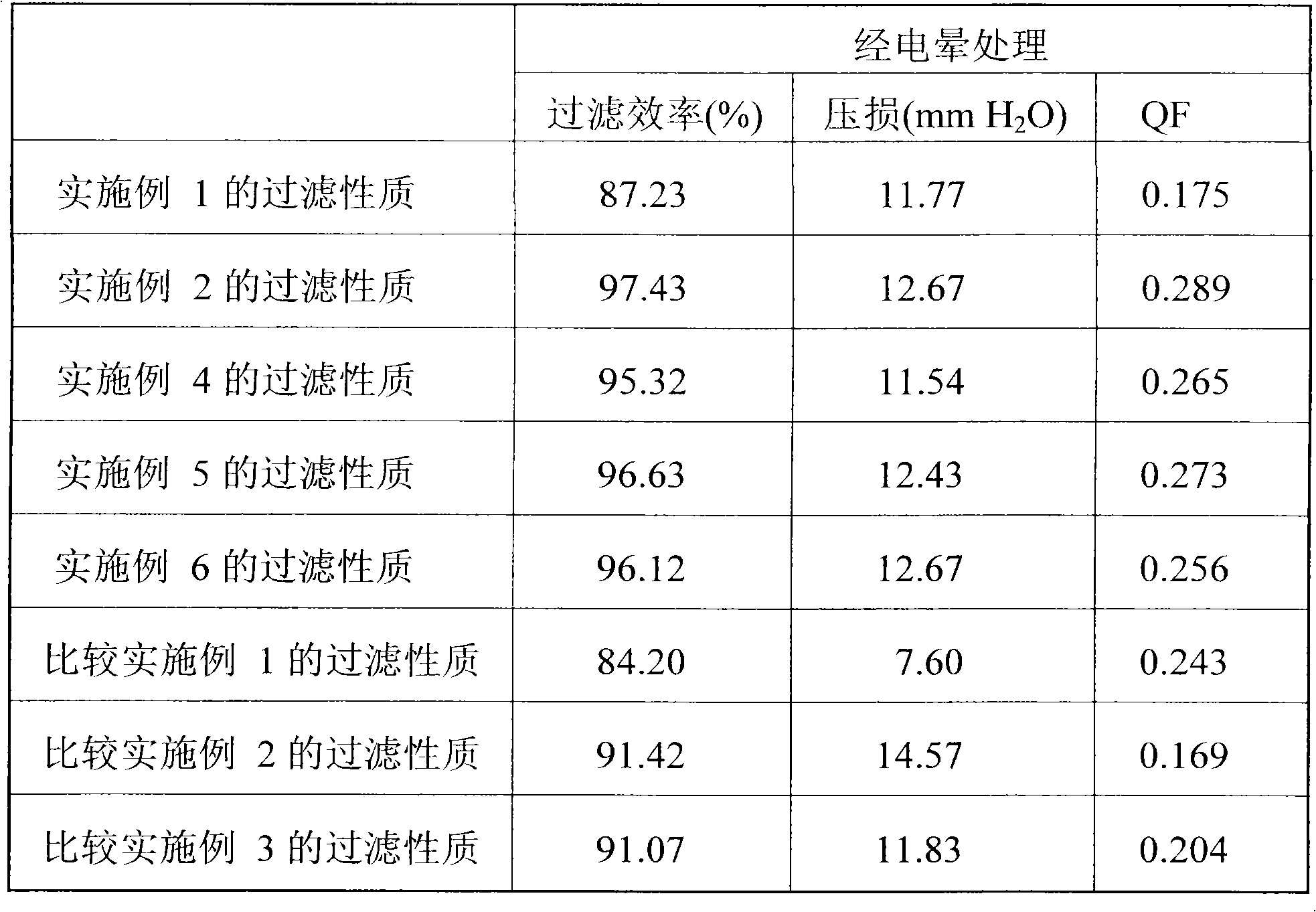
[0027] In this example, under the same electrospinning conditions as in Example 2, a composite nanofiber cotton web is formed, the difference is that the corona-treated single-layer composite nanofiber cotton web is laminated to form a double-layer composite nanofiber Cotton web, with 260nm particles, was measured by TSI 8130 at a gas flow rate of 5.3cm / sec, and its filtration properties are shown in Table 3.


PUM

PropertyMeasurementUnit
Thicknessaaaaaaaaaa
Fiber diameteraaaaaaaaaa
Average fiber diameteraaaaaaaaaa

Abstract

The invention relates to a nanofiber cotton net containing more than two different fiber diameter distributions, which is prepared from a polymer solution by an electrospinning method. More than two nanofibers with different fiber diameters are interlaced with each other in the process of electrospinning to form a nanofiber cotton net layer as a nanofiber filtration material of the invention. Thefiltration material has the characteristics of high efficiency and low pressure loss.

Description

technical field [0001] The invention relates to a nanofiber filter material for filtering particles in the air, and more particularly relates to the structure and forming method of the material. Background technique [0002] High efficiency particulate air (HEPA for short) is a kind of 260nm particles tested at a flow rate of 5.3cm / sec, its filtration efficiency is above 99.97%, and its pressure loss is 32mmH 2 Below O; if tested at a flow rate of 14cm / sec, the filtration efficiency is above 94%, and the pressure loss is 94mmH 2 O below the filter material. This filter material can be used in the air filtration of clean rooms or bio-clean rooms in semiconductor processes. In the above environment, it is necessary to use a stable HEPA filter to avoid airborne particles from damaging the products in the clean room or reducing the substances contained in the clean room. [0003] Currently commercially available HEPA filter materials are mainly composed of glass fiber or poly...

Claims


Application Information

Patent Timeline
IPC IPC(8): B01D39/16D04H1/56
Inventor 萧弘毅詹琼莹林嘉君郑淑蕙
Owner IND TECH RES INST
Why Eureka
Try Eureka