EMC inductor and manufacturing method thereof, EMI filter and switching power supply

A production method and technology of inductors, which are applied in transformers/inductor coils/windings/connections, inductors with magnetic cores, electrical components, etc., can solve problems such as filter design difficulties, improve anti-interference ability, and improve filtering effect of ability

Active Publication Date: 2010-03-03
VERTIV CORP
View PDF0 Cites 17 Cited by
  • Summary
  • Abstract
  • Description
  • Claims
  • Application Information

AI Technical Summary

Problems solved by technology

In the design of switching power supply, the disturbance of the frequency above 30MHz is mainly filtered and suppressed by the Y capacitor of the port, but for the disturbance of the nature of the voltage source, the capacity of the Y capacitor is required to be large, and the size of the Y capacitor is allowed to be used due to safety regulations and cost. and many other restrictions, which brings great difficulties to the filter design

Method used


Image

  • EMC inductor and manufacturing method thereof, EMI filter and switching power supply
  • EMC inductor and manufacturing method thereof, EMI filter and switching power supply
  • EMC inductor and manufacturing method thereof, EMI filter and switching power supply

Examples


Embodiment 1

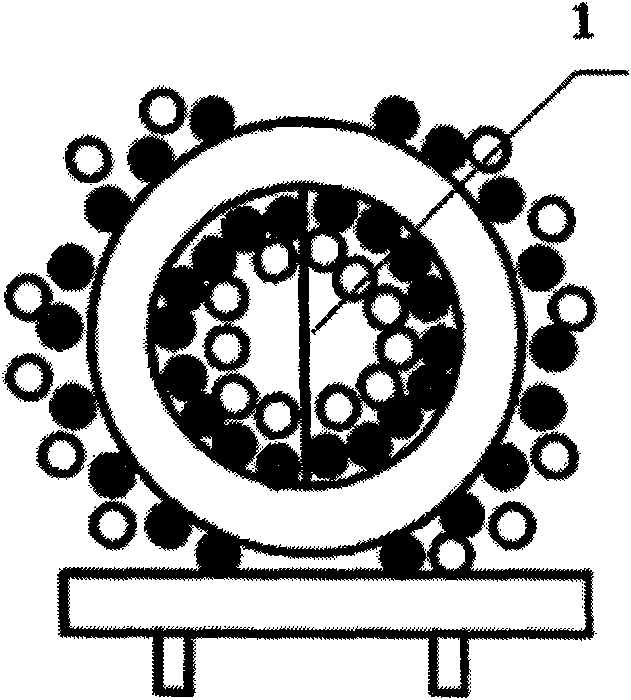
[0034] image 3 An EMC inductor of this embodiment is shown, which is a common mode inductor using a common ferrite core. The ferrite core is ring-shaped, and the winding includes a first winding layer and a second winding layer wound on the ferrite core. The first winding layer is evenly surrounded by the magnetic core, and the second winding layer is wound outside of the winding layer. In addition, an isolation baffle 1 for the common mode inductor is provided in the middle of the magnetic core, which is mainly provided for the convenience of processing the common mode inductor. The lead inductance and inter-turn capacitance generated by the first and second winding layers make the second resonance frequency of the common mode inductor in the 10MHz~200MHz frequency band, so that the common mode inductor has high impedance characteristics in this frequency band, so it can effectively suppress the high frequency in this frequency range. Frequency disturbance frequency point....

Embodiment 2

[0042] Please refer to Figure 6 , similar to the common mode inductor in Embodiment 1, the winding of the inductor includes a first winding layer and a second winding layer wound on a ferrite core, the first winding layer is evenly surrounded by the magnetic core, and the second winding layer Wrap around the outside of the first winding layer. The difference from Embodiment 1 is that an insulating layer 5 is added between the first winding layer and the second winding layer, and the insulating layer can be made of insulating tape or similar materials, so as to adjust the inter-turn capacitance Cp, and thus achieve the adjustment The role of the second resonance frequency point of the common mode inductor. Specifically, a layer of insulating tape 5 with a thickness of 0.15 mm is added between the two layers. In this embodiment, the first resonant frequency of the common mode inductor is set at about 400 KHz, the second resonant frequency is set at about 35 MHz, and the bandw...

Embodiment 3

[0045] Please refer to Figure 7 , and the difference from Embodiments 1 and 2 is that the winding of the common mode inductor includes not only the first and second winding layers, but also a third winding layer, which successively overlaps three layers on the magnetic core. The second resonant frequency point of the inductor can also be easily changed by increasing the number of winding layers. In this embodiment, the first resonant frequency of the common mode inductor is set at about 400 KHz, the second resonant frequency is set at about 35 MHz, and the bandwidth is about 10 MHz.

[0046] Similar to Example 1, please refer to the manufacturing steps of the common mode inductor Figure 5 . Wherein, in this embodiment, a winding layer is added without changing the winding leads. Compared with the two-layer stacked winding method, the three winding layers are concentratedly wound on part of the arc section of the toroidal core, the area of ​​the wound core is reduced, and ...


PUM

PropertyMeasurementUnit
electrical bandwidthaaaaaaaaaa

Abstract

The invention discloses an EMC inductor which comprises a magnetic core and a winding wound on the magnetic core, wherein lead inductance generated by the winding and turn-to-turn capacitance enable the second resonant frequency of the EMC inductor to be in a set frequency band, and the set frequency band is determined according to the frequency to which the interference signal to be inhibited corresponds. The invention also discloses an EMI filter comprising the EMC inductor and a switching power supply comprising the EMI filter. The invention also discloses a manufacturing method of the EMCinductor. The second resonant frequency of the EMC inductor can effectively inhibit the high-frequency noise in the frequency band, improves the high-frequency EMC performance of the inductor in the filter, and can realize high impedance characteristic the bandwidth of which is about 10MHz in the frequency band of 10MHz-200MHz.

Description

technical field [0001] The invention relates to EMC (Electro Magnetic Compatibility, ie electromagnetic compatibility) equipment, in particular to an EMC inductor, a manufacturing method thereof, an EMI filter and a switching power supply with the EMC filter. Background technique [0002] At present, the EMC inductors used in power modules, such as common mode inductors, generally focus on the design of frequency characteristics near the switching frequency of the module. Since the switching frequency is usually below 1MHz, all known EMC inductors are designed for frequency characteristics above 1MHz. Think less. In the design of switching power supply, the disturbance of the frequency above 30MHz is mainly filtered and suppressed by the Y capacitor of the port, but for the disturbance of the nature of the voltage source, the capacity of the Y capacitor is required to be large, and the size of the Y capacitor is allowed to be used due to safety regulations and cost. And so ...

Claims


Application Information

Patent Timeline
Patent Type & Authority Applications(China)
IPC IPC(8): H01F17/06H01F27/28H01F27/32H02M1/12
Inventor 邓凯
Owner VERTIV CORP
Why Eureka
Try Eureka