Ionic wind radiating device

A technology of heat dissipation device and ion wind, which is applied in laser cooling device, cooling/ventilation/heating transformation, phonon exciter, etc., can solve the problems of not being able to release heat in time, cumbersome manufacturing process, complicated device structure, etc. To achieve the effect of simple structure, reduce the overall volume and improve the heat dissipation efficiency

Inactive Publication Date: 2010-03-03
PHOEBUS VISION OPTO ELECTRONICS TECH +1
View PDF1 Cites 9 Cited by
  • Summary
  • Abstract
  • Description
  • Claims
  • Application Information

AI Technical Summary

Problems solved by technology

[0004] From the above description, it can be seen that the upper end of the device has a cover to form a channel with outlets on both sides, so that the ion wind cannot directly dissipate heat from the direction perpendicular to the heat sink, but only along the direction parallel to the heat sink. The ...

Method used


Image

  • Ionic wind radiating device
  • Ionic wind radiating device
  • Ionic wind radiating device

Examples


Embodiment Construction

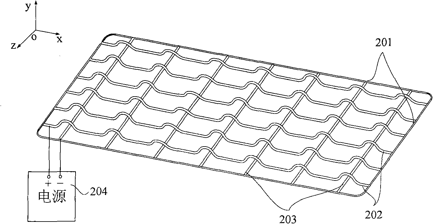
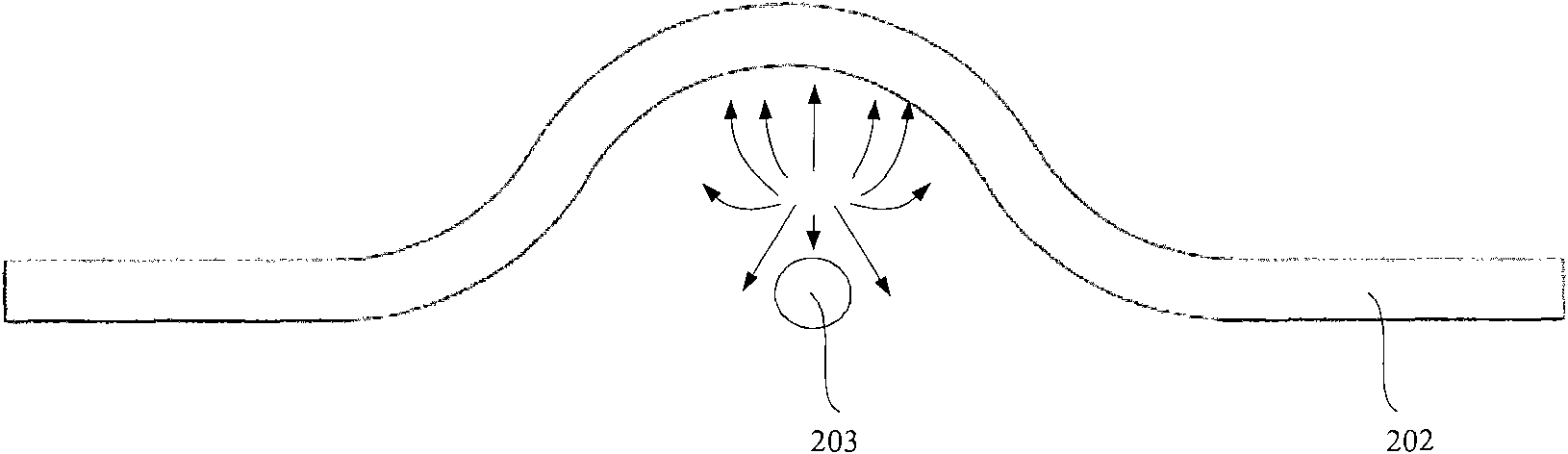
[0025] figure 2 A preferred embodiment of an ion wind cooling device of the present invention is shown. As can be seen from the figure, it includes a first group of conductive wires 202 and a second group of conductive wires 203 crossing each other, and the two ends of each conductive wire are fixed on the insulating frame 201, and all the conductive wires in the first group of conductive wires 202 The conductive wires are parallel to each other, all the conductive wires in the second group of conductive wires 203 are also parallel to each other, and the first group of conductive wires 202 and the second group of conductive wires 203 are perpendicular to each other in the xoz plane to form a heat dissipation network. At the intersection of each conductive line of the line 202 and each conductive line of the second group of conductive lines 203, the first group of conductive lines 202 protrude in a circular arc shape along the positive direction of the y-axis, and straddle the...


PUM


Abstract

The invention provides an ionic wind radiating device, which is characterized by comprising a power supply and a radiating net formed by mutually intersecting a first group of conductive wires comprising two or more than two conductive wires and a second group of conductive wires comprising two or more than two conductive wires, wherein the first group of conductive wires are electrically connected to one output end of the power supply; the second group of conductive wires are electrically connected to another output end of the power supply; in addition, at the position of each intersection, the first group of conductive wires have bumps which face the same direction and are vertical to the plane of the radiating net so as to stride over the corresponding second group of conductive wires which are intersected with the first group of conductive wires, and the first and the second groups of conductive wires are mutually insulated.

Description

technical field [0001] The invention relates to the technical field of radiators, in particular to a device for using ion wind to dissipate heat. Background technique [0002] Traditional laser cooling methods are mostly fan cooling, water cooling, conduction cooling and other cooling methods. These cooling methods have the disadvantages of high noise, easy pollution, and large volume. [0003] The U.S. patent that publication number is US7190587 discloses a kind of fanless ion wind cooling device, as figure 1 As shown, it includes a heat sink 101 , a bottom surface 102 , a protrusion 103 , a cover 104 , wires 105 , a wire support 106 , a fixing part 107 , a power source 108 and an accelerator 109 . The heat sink 101 has a fixing part 107 and is fixed on the heating part of the component by the fixing part 107 . The wire support 106 is used to place the wires 105 . The wires 105 are located between two adjacent protrusions 103 and kept parallel to the protrusions 103 . Th...

Claims


Application Information

Patent Timeline
IPC IPC(8): H01S3/04H01S3/042H01S5/024H05K5/02H05K7/20
Inventor 王斌房涛成华梅东滨贾中达
Owner PHOEBUS VISION OPTO ELECTRONICS TECH
Why Eureka
Try Eureka