CMOS difference radio-frequency signal amplitude detection circuit

A radio frequency signal and amplitude detection technology, applied in logic circuits, measuring electrical variables, noise figure or signal-to-noise ratio measurement, etc., can solve problems such as limitations, achieve high amplitude detection gain, reduce costs, and be easy to mass produce and debug Effect

Active Publication Date: 2010-03-10
斯凯瑞利(北京)科技有限公司
View PDF0 Cites 9 Cited by
  • Summary
  • Abstract
  • Description
  • Claims
  • Application Information

AI Technical Summary

Problems solved by technology

[0003] CMOS circuits are used for signal amplitude detection. Due to the limitation of high threshold voltage, high input impedance and large parasitic capacitance, they can only be used for detection and amplitude detection of low-frequency large signals.

Method used


Image

  • CMOS difference radio-frequency signal amplitude detection circuit
  • CMOS difference radio-frequency signal amplitude detection circuit
  • CMOS difference radio-frequency signal amplitude detection circuit

Examples


Embodiment Construction

[0017] Below in conjunction with accompanying drawing and embodiment the present invention will be described in further detail:

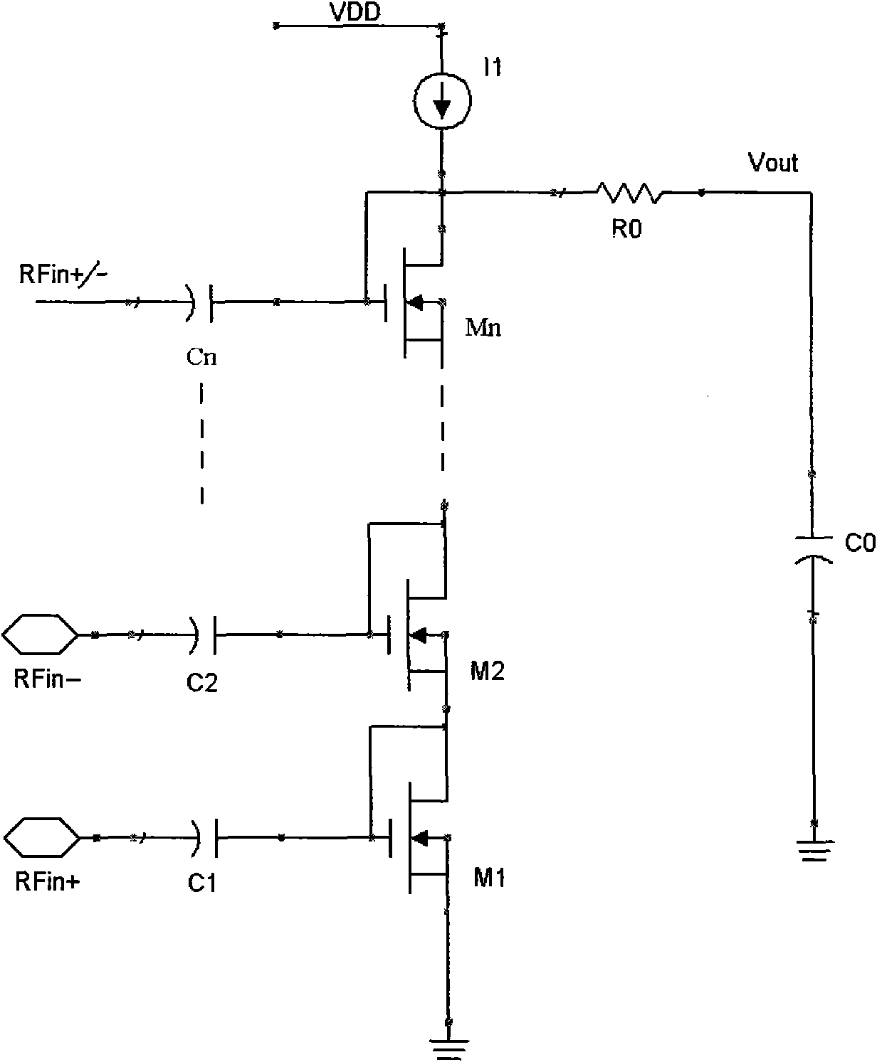
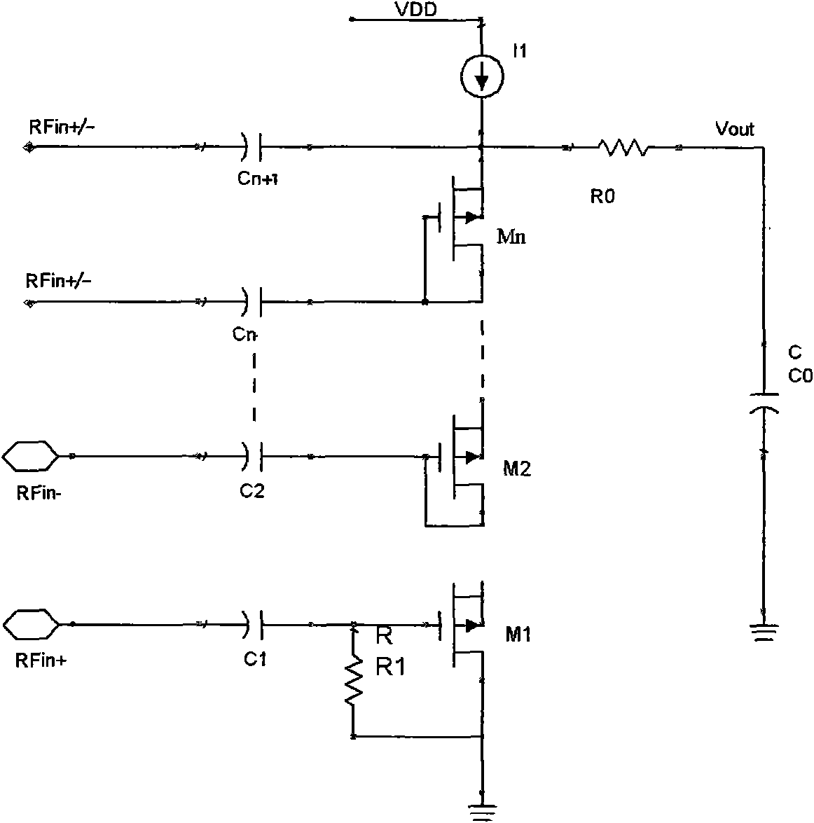
[0018] Such as figure 1 As shown in (a), the MOS transistor M1 is biased by the current source I1, and the RF signal of Rfin is single-ended input through C1. The filter resistor R0 and the capacitor C0 filter out the radio frequency signal to obtain a DC component Vout. When M1 works in the strong inversion state, the relationship between the current and the voltage is a square ratio, which is formula (1):

[0019] I1=K*(Vin*sin(wt)+Vout-Vth) 2 (1)

[0020] Since I1 is constant, the relationship between the change of ΔVout and the amplitude Vin of the RF signal of Rfin can be obtained as formula (2):

[0021] ΔVout=Vin 2 / [4*(Vout-Vth)] (2)

[0022] When M1 works in the weak inversion state, the current and voltage have an exponential relationship, which is formula (3):

[0023] I1=I0*exp{[Vin*sin(wt)+Vout-Vth]*q / nKT} (3)

[002...


PUM


Abstract

The invention discloses a CMOS difference radio-frequency signal amplitude detection circuit, being composed of MOS transistors from M1 to Mn which work under the weak inversion polarization and a filter resistance R0 and a capacitance C0; the MOS transistors from M1 to Mn are serially connected, and the polarization is provided by a current source I1, the grids or drains of the transistors from M1 to Mn are respectively connected with the input positive end Rfin+ of a radio-frequency signal or the input negative end Rfin- of the radio-frequency signal through the capacitances from C1 to Cn, and an amplitude detection result is output by the filter resistance R0 and the capacitance C0, the current change of the MOS transistors under the weak inversion polarization submits to index property, and higher amplitude detection gain is obtained compared with square frequency characteristics, particularly for the weak signal detection, the gain is obvious, and the power consumption is low andis approximate to zero consumption; a plurality of the MOS transistors are serially connected to lead amplitude detection output of each MOS transistor to be serially added, thereby obtaining n timesof detection gain; meanwhile, input impedances of radio-frequency inputs of all MOS transistors are connected in parallel, the whole input impedance value is reduced by n times, the requirements of Qvalue that a high-frequency signal is input to a matching circuit is reduced, so as to realize to be directly connected with a radio-frequency antenna; the differential signal input is adopted, so asto be easy for chip integration and reduce the requirements of chip encapsulation. The circuit is particularly suitable for being applied to wake-up signal detection in a short range communication system and weak radio-frequency signal detection in an RFID system.

Description

Technical field [0001] The invention relates to a radio frequency signal amplitude detection circuit realized based on CMOS, in particular to the wake-up signal detection in the microwave dedicated short-range communication and the weak radio frequency signal detection in the RFID system. Background technique [0002] Dedicated Short Range Communication (DSRC) technology is mainly implemented based on wireless communication, and is used in electronic toll collection (ETC), automatic vehicle identification and other fields. The mobile receiving end usually wakes up and enters the communication state by detecting the strength of the radio frequency signal, and demodulates the amplitude of the radio frequency signal. The communication frequency band of DSRC in China is 5.8GHz, and the vehicle electronic label (On Board Unit, referred to as OBU) and road test equipment (Road Side Unit, referred to as RSU) work in this way. [0003] CMOS circuits are used for signal amplitude de...

Claims


Application Information

Patent Timeline
Patent Type & Authority Applications(China)
IPC IPC(8): G01R29/00G01R29/26H03K19/0948
CPCY02B60/50
Inventor 王树甫
Owner 斯凯瑞利(北京)科技有限公司
Why Eureka
Try Eureka