Electrode frame structure for redox flow cell

A liquid flow battery and electrode frame technology, which is applied to fuel cell components, fuel cells, circuits, etc., can solve problems affecting battery efficiency and life, loss of protection, and easy deformation, so as to prolong life and avoid electric shocks. Chemical corrosion, the effect of easy assembly in piles

Inactive Publication Date: 2010-03-10
DALIAN INST OF CHEM PHYSICS CHINESE ACAD OF SCI +1
View PDF2 Cites 25 Cited by
  • Summary
  • Abstract
  • Description
  • Claims
  • Application Information

AI Technical Summary

Problems solved by technology

However, the structure is more complicated, the assembly is difficult, the cost is more expensive, and it is not conducive to industrialization
The patent "Battery unit frame for redox flow battery and redox flow battery" (application number: 02811590.2) jointly applied by Japan's Sumitomo Electric Industries Co., Ltd. and Kansai Electric Power Co., Ltd. mentions that the single-cell structure adopts the flow channel groove to place 0.1 ~0.3mm thick protective plate to protect the bipolar plate. During the actual assembly process, it is easy to deform and lose its protective effect, which seriously affects the efficiency and life of the battery.

Method used


Image

  • Electrode frame structure for redox flow cell
  • Electrode frame structure for redox flow cell
  • Electrode frame structure for redox flow cell

Examples


Embodiment 1

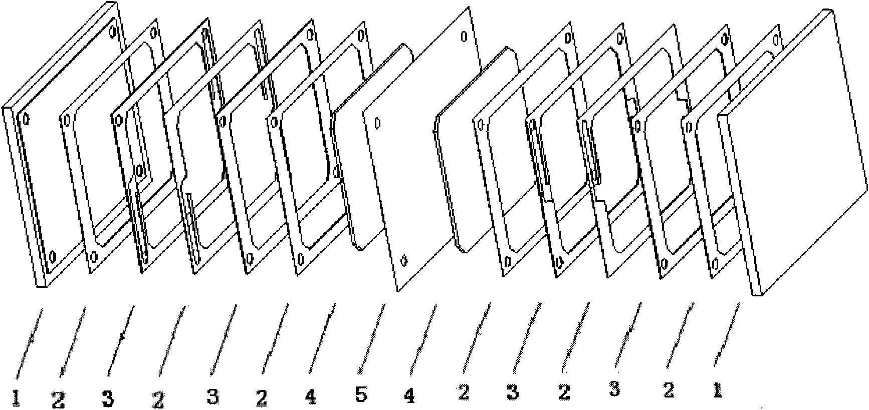
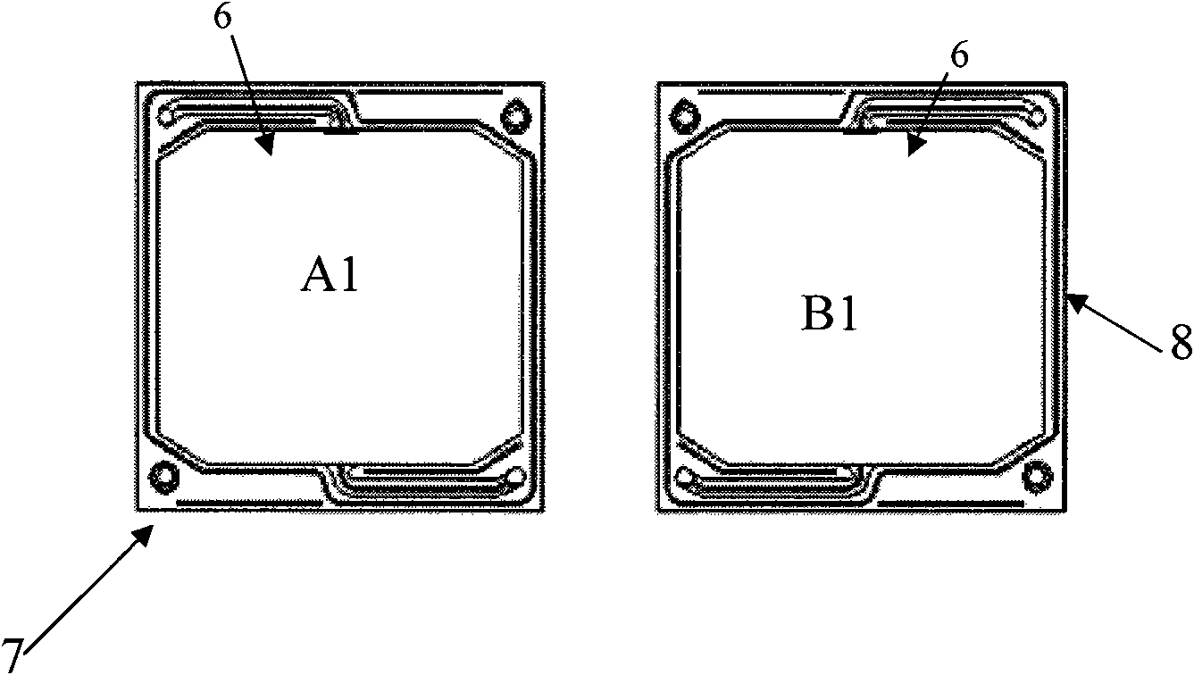
[0023] Battery structure such as figure 1 As shown, the electrode frame is as figure 2 As shown, it is a built-in fluid flow channel formed by two square frames (A1 and B1) having mirror-symmetrical fluid flow channels, and the fluid channels are buckled together inwardly. Two square frames are glued together to form a built-in structure. The frame material is PVC.

[0024] Dimensions of the electrode frame: length 300cm, width 400cm

[0025] Electrode area: 875cm2

[0026] Number of single batteries: 13

[0027] Stack charge and discharge voltage efficiency 89%, coulombic efficiency 90.5%, energy efficiency 80.5%

Embodiment 2

[0029] Battery structure such as figure 1 As shown, the electrode frame is as figure 2 As shown, it is a built-in fluid flow channel formed by two square frames (A1 and B1) having mirror-symmetrical fluid flow channels, and the fluid channels are buckled together inwardly. The two boxes are sealed with sealing material and face-sealed, and a built-in structure is formed through assembly force. The sealing material is fluorine rubber, and the frame material is PE.

[0030] Dimensions of the electrode frame: length 400cm, width 500cm

[0031] Electrode area: 1700cm2

[0032] Number of batteries: 15

[0033] The charging and discharging voltage efficiency of the stack is 87%, the Coulombic efficiency is 93.5%, and the energy efficiency is 81.4%.

Embodiment 3

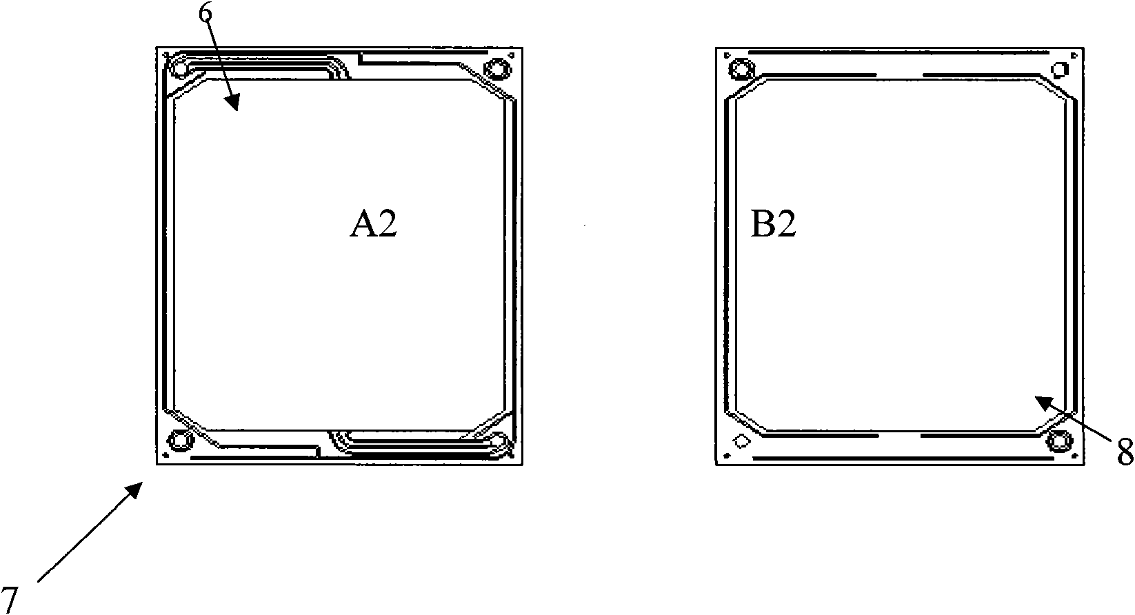
[0035] Battery structure such as figure 1 As shown, the electrode frame is as image 3 As shown, it is composed of two square frames with the same shape and size (A2 and B2), where the A2 frame is engraved with inlet and outlet flow channels, while the B2 frame has no engraved fluid flow channels, and the A2 frame The flow channel is inwardly buckled with the B2 frame to form a built-in fluid flow channel. The two boxes are sealed with sealing material and face-sealed, and a built-in structure is formed through assembly force. The sealing material is fluorine rubber, and the frame material is PP.

[0036] Dimensions of the electrode frame: length 400cm, width 500cm

[0037] Electrode area: 1700cm2

[0038] Number of batteries: 20

[0039] The charging and discharging voltage efficiency of the stack is 89%, the Coulombic efficiency is 91.5%, and the energy efficiency is 81.5%.


PUM

PropertyMeasurementUnit
areaaaaaaaaaaa
areaaaaaaaaaaa
current efficiencyaaaaaaaaaa

Abstract

The invention relates to an electrode frame for a redox flow cell, in particular to an electrode frame structure for an all-vanadium redox flow cell, which is formed by fastening two frame bodies of which the shapes and sizes are completely same; a plane where the two frame bodies are mutually fastened is a fastening surface; and the fastening surface of at least one frame body is provided with afluid channel which is fastened into a border to form an embedded-structure electrolyte inlet and outlet channel. The structure increases the resistance of an electrolyte channel branch, reduces leakage current, avoids thermogalvaniccorrosion in charging and discharging processes, and prolongs the service life of the cell (stack).

Description

technical field [0001] The invention relates to an electrode frame of a redox flow battery, in particular to an electrode frame structure of an all-vanadium redox flow battery. Background technique [0002] Electric energy is difficult to store and indispensable. Its production must meet the demand for electricity at any time. Therefore, people have been looking for economical and feasible energy storage technologies to solve the contradiction between supply and demand and decouple the production of electric energy from demand. In addition, electric energy storage plays an important role in electric energy management, grid auxiliary services, voltage control, renewable energy utilization, and large-scale uninterruptible power supplies. If combined with large-scale thermal power generation, it can reduce the peak capacity of power stations, reduce power generation costs, and reduce pollution. If it is combined with renewable energy such as wind power and tidal energy, it can ...

Claims


Application Information

Patent Timeline
Patent Type & Authority Applications(China)
IPC IPC(8): H01M8/02H01M8/0273
CPCY02E60/50
Inventor 高素军张华民陈剑韩希刘景开郝玥
Owner DALIAN INST OF CHEM PHYSICS CHINESE ACAD OF SCI
Why Eureka
Try Eureka