

Measurement method of thickness of subsurface damaged layer of bucky optical material
A technology of subsurface damage and optical materials, applied in the direction of measuring devices, using optical devices, and material analysis using radiation diffraction, etc., can solve problems such as unexplained measurements, unintuitive image processing results, and practical applications that are not suitable for engineering. Achieve strong engineering applicability and high precision
- Summary
- Abstract
- Description
- Claims
- Application Information
AI Technical Summary
Problems solved by technology
Method used
Image

Examples
Embodiment 1
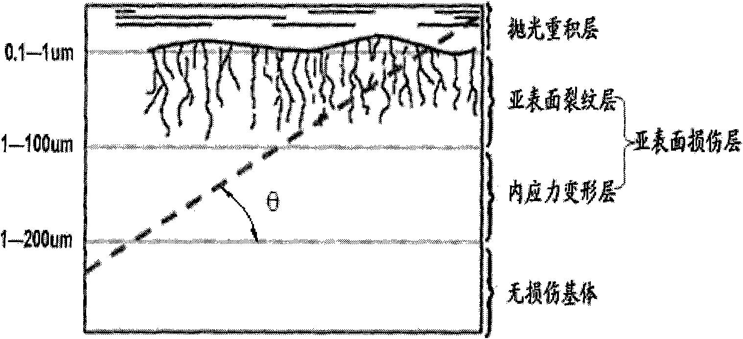
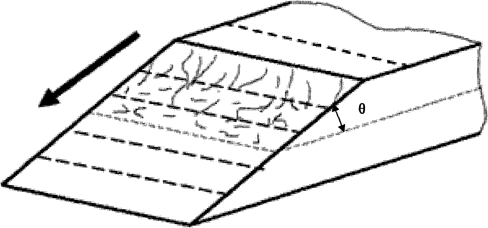
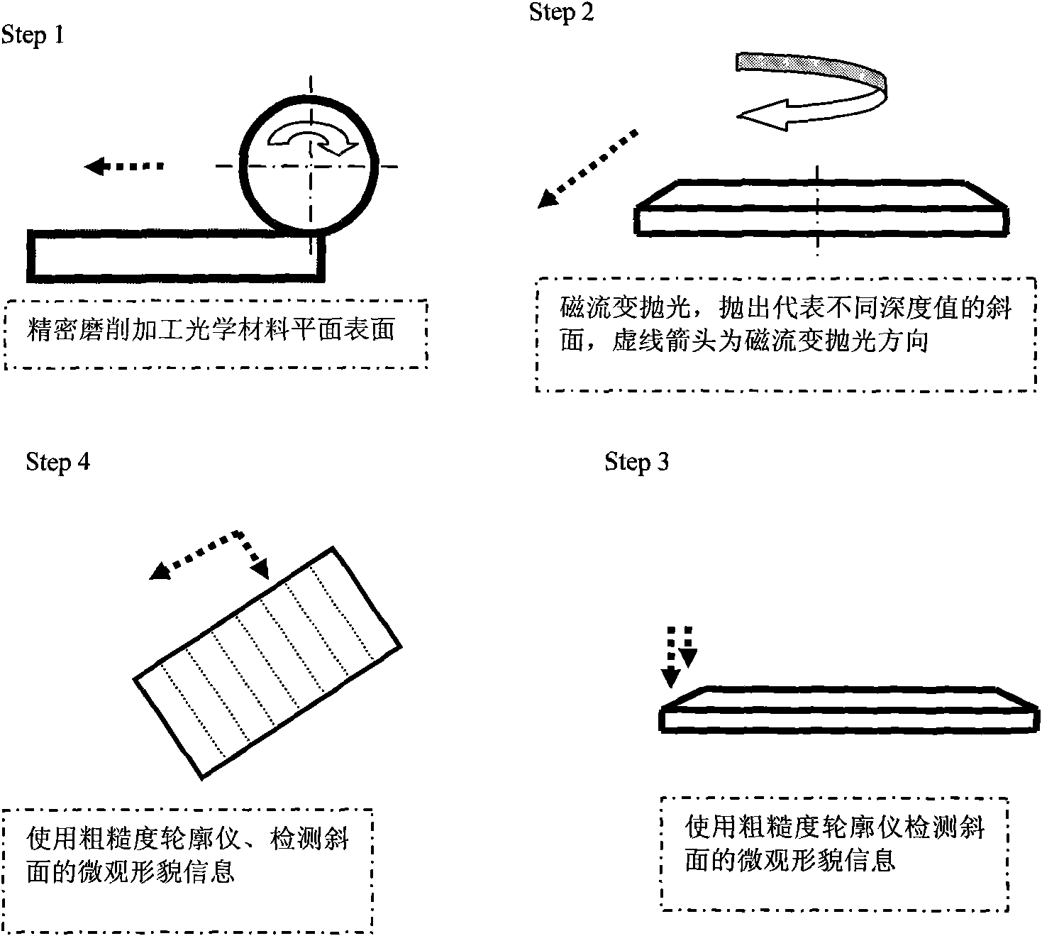
[0032] figure 2 , image 3 A processing example of an optical glass flat sample is shown. Measurement of the subsurface damage layer thickness of a K9 optical glass flat sample: in image 3 Step1 Subsurface damage detection is performed on the optical surface after W20 abrasive grinding for 20 minutes: image 3 As shown in Step2, the magneto-rheological polishing process is used to process a tiny slope with an inclination angle of θ=6' ( figure 2 ), along the direction of magnetorheological polishing indicated by the arrow, the profile information at different depths from the original plane can be reflected on the slope. Use HF acid corrosion reagent to treat the slope after magnetorheological polishing, clean the surface and further expose and enlarge the cracks on the slope. Use the roughness profiler to scan from the dotted line near the start boundary of the slope ( figure 2 , image 3 Step3), feed along the slope along the direction of the arrow according to the ...
Embodiment 2
[0035] Such as Image 6 As shown, a specific measurement example of the thickness of the subsurface damage layer of an optical ceramic spherical mirror, in Image 6 Subsurface damage detection is performed on the optical surface after W40 abrasive grinding for 20 minutes in Step 1: Image 6 Shown in Step 2: using the magnetorheological polishing process to throw a detection circular plane on a spherical sample with a radius of curvature R, and its horizontal radius is r. The cutting plane and the original spherical surface form a spherical cap ( Image 6 Step2), the circumference of the plane is shallower than the original surface, and the center of the circle is deeper than the original surface. Use corrosive chemical reagents to treat the cut plane to enlarge the exposure of subsurface cracks on the cut plane; Image 6 In Step3 and Step4: Use the white light interferometer to scan the circular plane from the circumference of the point P 1 (X 1 , Y 1 ,Z 1 ) along the r...
PUM
 Abstract
Description
Claims
Application Information