Apparatus for producing reflective membrane with microprism array structure

A technology of array structure and production equipment, applied in optics, optical components, instruments, etc., can solve the limitation of microprism hardness, scratch resistance, heat resistance and solvent resistance, long heating and cooling time, and limitation of processing and use. performance and other issues, to achieve the effects of good product consistency, improved performance, excellent hardness and scratch resistance

Active Publication Date: 2010-03-17
ZHEJIANG DAOMING OPTOELECTRONICS TECH
View PDF1 Cites 38 Cited by
  • Summary
  • Abstract
  • Description
  • Claims
  • Application Information

AI Technical Summary

Problems solved by technology

[0006] 1. The film needs to be heated above the glass transition temperature in the heating station during the microprism forming process, and its suitable temperature is 425-475°F, that is, 218-246°C, and then cooled to Below the glass transition temperature, it needs to be cooled to 180°F, which is equivalent to below 82°C. The temperature difference between heating and cooling is large, and the film has a large specific heat, so its heating and cooling time is relatively long. For a certain As far as the length of the endless belt mold is concerned, this will inevitably affect its production speed. The laminated film disclosed in the invention patent passes through the embossing device at a speed of 0.8-1.2 m / min, resulting in a reduction in its work efficiency
[0007] 2. During the above-mentioned long-time heating and cooling process, the molded product will be deformed, resulting in poor consistency of the product
[0008] 3. Since the film used is a thermoplastic material, the hardness, scratch resistance, heat resistance and solvent resistance of the microprism formed by the thermoplastic resin with a linear structure are bound to be restricted, which also restricts the subsequent processing and use performance of the product

Method used


Image

  • Apparatus for producing reflective membrane with microprism array structure
  • Apparatus for producing reflective membrane with microprism array structure
  • Apparatus for producing reflective membrane with microprism array structure

Examples


Embodiment 1

[0044] Such as figure 1 Shown, the production equipment with the reflective film of microprism array structure comprises annular belt mold 6, coating device 1, drying device 2, heating film pressing device 3, UV curing device 4 and cooling device 5; Figure 9 As shown, the annular belt mold 6 has an inner surface 61 and an outer surface 62, and its outer surface 62 has a continuous precision microprism array structure 63 in a convex shape; as Figure 8 and Figure 9 As shown, the coating device 1 coats the photosensitive resin 81 on one side surface of the resin film 82, and the resin film 82 coated with the photosensitive resin 81 is dried by the drying device 2, and then the The side surface of the resin film 82 coated with the photosensitive resin 81 is closely attached to the outer surface 62 of the annular belt mold 6 to be heated and pressed by the heating film pressing device 3, so that the photosensitive resin 81 fills the gaps of the raised microprism structures, an...

Embodiment 2

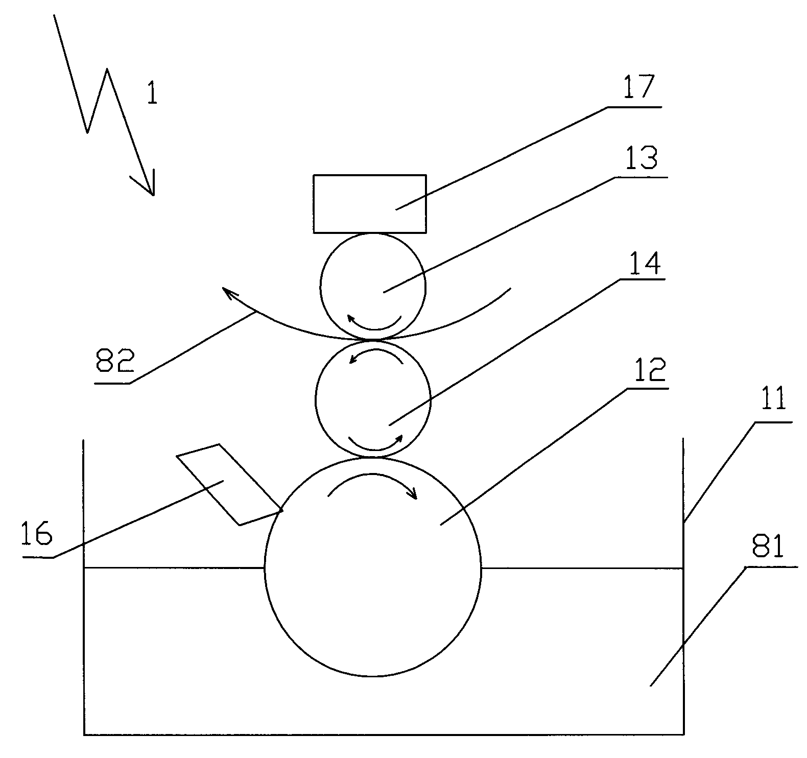
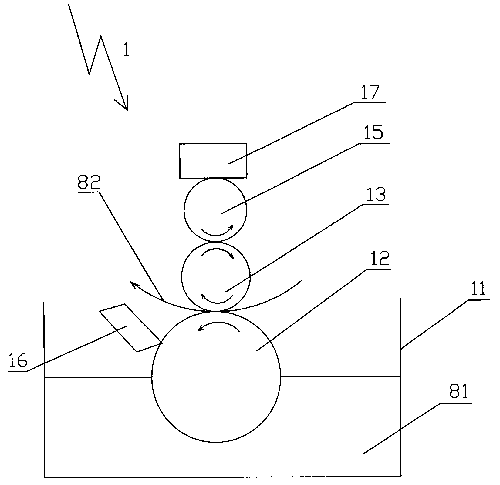
[0054] Such as image 3 As shown, the coating device 1 includes a trough 11, a feed roller 12, a squeeze roller 13, a booster roller 15 and a free-rising pressurization system 17 directly connected to the booster roller 15. The pressurizing roller 15 is positioned above the extrusion roller 13, and the resin film 82 is positioned above the feed roller 12 and below the extrusion roller 13, and the photosensitive resin 81 is housed in the storage tank 11. The material roller 12 is immersed in the described feed tank; during the rotation of the material roller 12, the photosensitive resin 81 flows to the surface of the material roller 12; The direction of motion in the direction is the same. Through the action of the pressure system 17 on the pressurizing roller 15 and the extrusion roller 13, the resin film 82 is close to and attached to the upper feed roller 13, and on the upper feed roller 12 and the extrusion roller. The tangent position of the roller 13 transfers the photos...

Embodiment 3

[0057] Such as Figure 4 As shown, the coating device 1 includes a storage tank 111, a feed roller 12, a transfer roller 14, a squeeze roller 13, a freely lifting pressurizing system 17 directly connected to the squeeze roller 13, a recovery tank 112 and The scraper 161 is a hollow cavity, the delivery pipe 18 is connected between the cavity of the scraper 161 and the bucket 111, and the delivery pipe 18 transports the photosensitive resin 81 in the bucket 111 to the scraper through the delivery pump In the cavity of 161, the side of the scraper 161 facing the feeding roller 12 basically coincides with the feeding roller 12, and there is a slit on this surface, and the photosensitive resin 81 flowing out from the cavity of the scraper 161 follows the feeding roller The rotation flow of 12 transfers to the outer surface of feeding roller 12, and described resin film 82 is positioned at the top of feeding roller 12 and transfer roller 14, the below of squeeze roller 13, in the p...


PUM


Abstract

The invention relates to an apparatus for producing a reflective membrane with a microprism array structure and solves the defects in the prior art that the hardness, scratch resistance, heat resistance and solvent resistance of microprisms are disappointing, the product consistency is poorer, the production speed is lower, the work efficiency is not high, and the like. The apparatus comprises anannular strip-shaped mould, a heating membrane pressing device and a cooling device, wherein the annular strip-shaped mould is provided with an inner surface and an outer surface which is provided with a convex continuous precise microprism array structure. The apparatus also comprises a coating device, a drying device and a UV curing device. By adding the coating device, the drying device and theUV curing device, the microprism structure is formed after the UV curing of photosensitive resin, the hardness, scratch resistance, heat resistance and solvent resistance of microprism of the microprism structure are greatly improved, and the product consistency is fine. In addition, the apparatus can also obviously improve the production speed and the work efficiency.

Description

technical field [0001] The invention relates to a production device of a reflective film, in particular to a production device of a reflective film with a microprism array structure. Background technique [0002] Reflective materials with a microprism array structure are more and more widely used in various road traffic safety facilities, signs and vehicle passive safety protection devices due to their excellent retroreflective properties. The so-called microprism array structure refers to a structure composed of three mutually perpendicular planes, which can perform total internal reflection on the incident light from the front surface, thereby greatly improving the reflection efficiency of the incident light. The plane based on this structure is not limited to a certain size or shape, nor is it limited to the direction of the optical axis of the prism unit. This structure is usually called "cube pyramid", "triangular pyramid" or "trihedron" . [0003] According to the di...

Claims


Application Information

Patent Timeline
Patent Type & Authority Applications(China)
IPC IPC(8): G02B5/124B29C59/04
Inventor 胡智雄胡智彪王嘉伟
Owner ZHEJIANG DAOMING OPTOELECTRONICS TECH
Why Eureka
Try Eureka