Method for forming shallow trench isolation structure and shallow trench isolation structure

An isolation structure and shallow trench technology, applied in the manufacturing of electrical components, electrical solid-state devices, semiconductor/solid-state devices, etc., can solve the problems of reliability device failure, integrated circuit performance degradation, uneven polysilicon contour, etc., and achieve uniform contour. , Guaranteed performance effect

Inactive Publication Date: 2010-03-17
SEMICONDUCTOR MANUFACTURING INTERNATIONAL (BEIJING) CORP
View PDF0 Cites 19 Cited by
  • Summary
  • Abstract
  • Description
  • Claims
  • Application Information

AI Technical Summary

Problems solved by technology

Due to the variable height difference in the formation of the STI structure, the polysilicon profile will become uneven, and there will be polysilicon residues after the polysilicon is etched later, and these polysilicon residues will cause short circuits or leaks that damage the STI isolation function. current path, degrading the performance of the integrated circuit, leading to reliability issues and device failure

Method used


Image

  • Method for forming shallow trench isolation structure and shallow trench isolation structure
  • Method for forming shallow trench isolation structure and shallow trench isolation structure
  • Method for forming shallow trench isolation structure and shallow trench isolation structure

Examples


Embodiment Construction

[0037] Although the invention will be described in more detail below with reference to the accompanying drawings, in which preferred embodiments of the invention are shown, it should be understood that those skilled in the art can modify the invention described herein and still achieve the advantageous effects of the invention. Therefore, the following description should be understood as a broad instruction for those skilled in the art, rather than as a limitation of the present invention.

[0038] In the following paragraphs the invention is described more specifically by way of example with reference to the accompanying drawings. Advantages and features of the present invention will become apparent from the following description and claims. It should be noted that the drawings are all in a very simplified form and use imprecise ratios, which are only used to facilitate and clearly assist the purpose of illustrating the embodiments of the present invention.

[0039] The pres...


PUM

PropertyMeasurementUnit
thicknessaaaaaaaaaa
thicknessaaaaaaaaaa
thicknessaaaaaaaaaa

Abstract

The invention discloses a method for forming a shallow trench isolation structure and the shallow trench isolation structure. In the process of forming the shallow trench isolation structure, double-layer hard masking films are adopted, namely that an oxide, such as a silicon oxide film is additionally arranged on an original nitride, such as a silicon nitride film. Because the selection ratio ofetching to the silicon oxide is higher than that of the silicon nitride, the surface of the silicon nitride film can not be damaged in the etching process, and the surface of the silicon nitride filmis still smooth and uniform after being etched. The invention ensures that after CMP, the height difference generated between each active region and each adjacent field oxide region on same Wafer plane is consistent, thereby ensuring a uniform outline of grown multi-crystal silicon and ensuring the performance of an integrated circuit.

Description

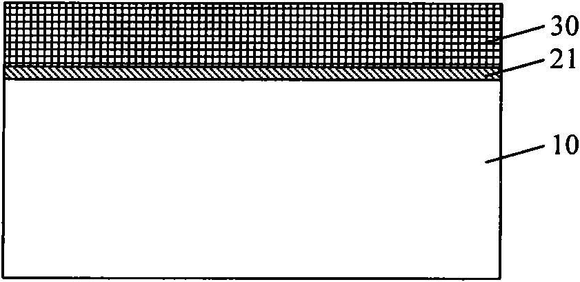
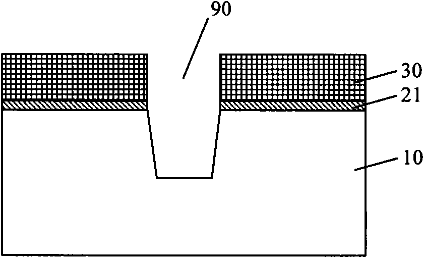
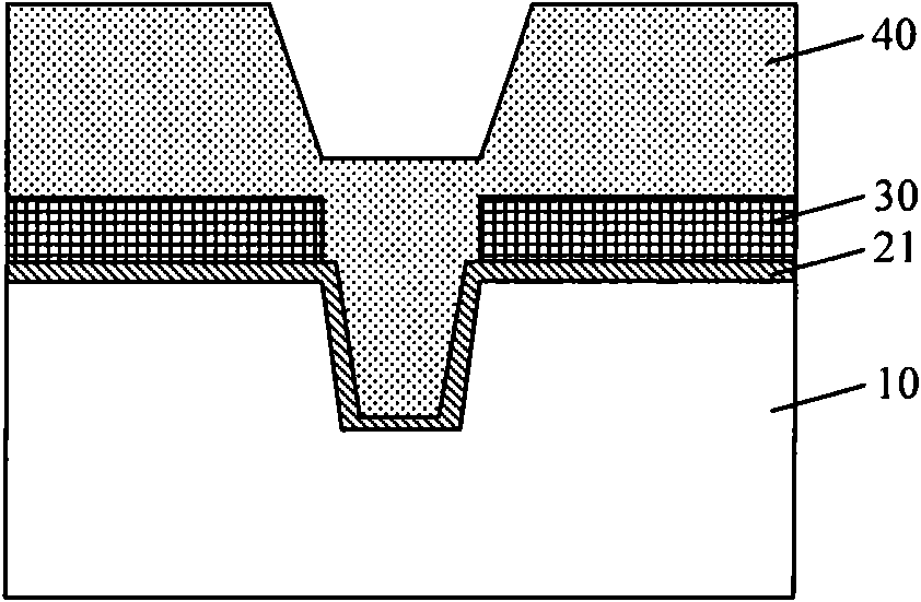
technical field [0001] The invention relates to the technical field of semiconductor manufacturing, in particular to a method for forming a shallow trench isolation structure and the shallow trench isolation structure. Background technique [0002] With the rapid development of semiconductor manufacturing technology, the integrated circuit manufacturing process has entered the deep submicron era, and the size of semiconductor devices and the isolation structure for isolating semiconductor devices have also shrunk. At a process node below 0.13us, such as a 65nm or even a 45nm node process, the isolation layer between elements in the active area (AA, Active area) of the semiconductor device is mostly formed by a shallow trench isolation (STI, Shallowtrench isolation) process. [0003] Currently, a hard mask such as a silicon nitride (SiN) film is used in forming the shallow trench isolation structure. Figure 1a ~ Figure 1e It is a simplified cross-sectional schematic diagram ...

Claims


Application Information

Patent Timeline
Patent Type & Authority Applications(China)
IPC IPC(8): H01L21/762H01L27/04
Inventor 韩秋华陈海华张世谋韩宝东
Owner SEMICONDUCTOR MANUFACTURING INTERNATIONAL (BEIJING) CORP
Why Eureka
Try Eureka