
Microphone amplifier

A technology of microphone amplifier and current amplification, which is applied in the field of microphones and can solve the problems of reduced reliability and high noise

Inactive Publication Date: 2010-03-17
RFSEMI TECH INC
View PDF1 Cites 6 Cited by
  • Summary
  • Abstract
  • Description
  • Claims
  • Application Information

AI Technical Summary

Problems solved by technology

[0011] Other methods include a differential amplifier method using CMOS elements (Korean Laid-Open Patent No. 10-2006-0113925), but CMOS elements are more noisy than JFET elements
Moreover, the oxide film of the gate is only a few hundred angstroms (Angstrom), and its ultra-thin thickness is easily affected by external electrical shocks, which reduces reliability.

Method used


Image

  • Microphone amplifier
  • Microphone amplifier
  • Microphone amplifier

Examples


Embodiment Construction

[0034] The preferred embodiments of the present invention will be further described below in conjunction with the accompanying drawings.

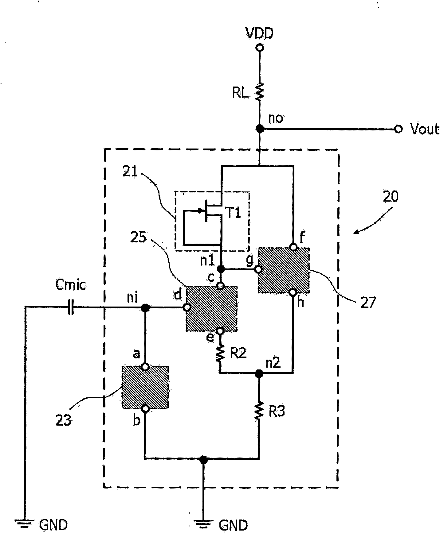
[0035] figure 2 It is the circuit diagram of the capacitive microphone amplifier of the present invention.

[0036] see figure 2 , the signal input terminal of the microphone amplifier 20 of the present invention is a node (ni), and the voice signal recognized by the electrostatic capacitance (Cmic) is converted into an electrical signal and then transmitted to the node (ni). The electrical signal flowing into the signal input terminal needs to be amplified by the voltage-current conversion unit 25 and converted into a current because it is too weak.

[0037]One end (a) of the bias unit 23 is connected to the first node (ni), and the other end (b) is connected to the ground terminal (GND). The bias unit 23 can adjust the electrical signal flowing from the electrostatic capacitance (Cmic) The bias (bias) to make it stable.

[0038] The...


PUM


Abstract

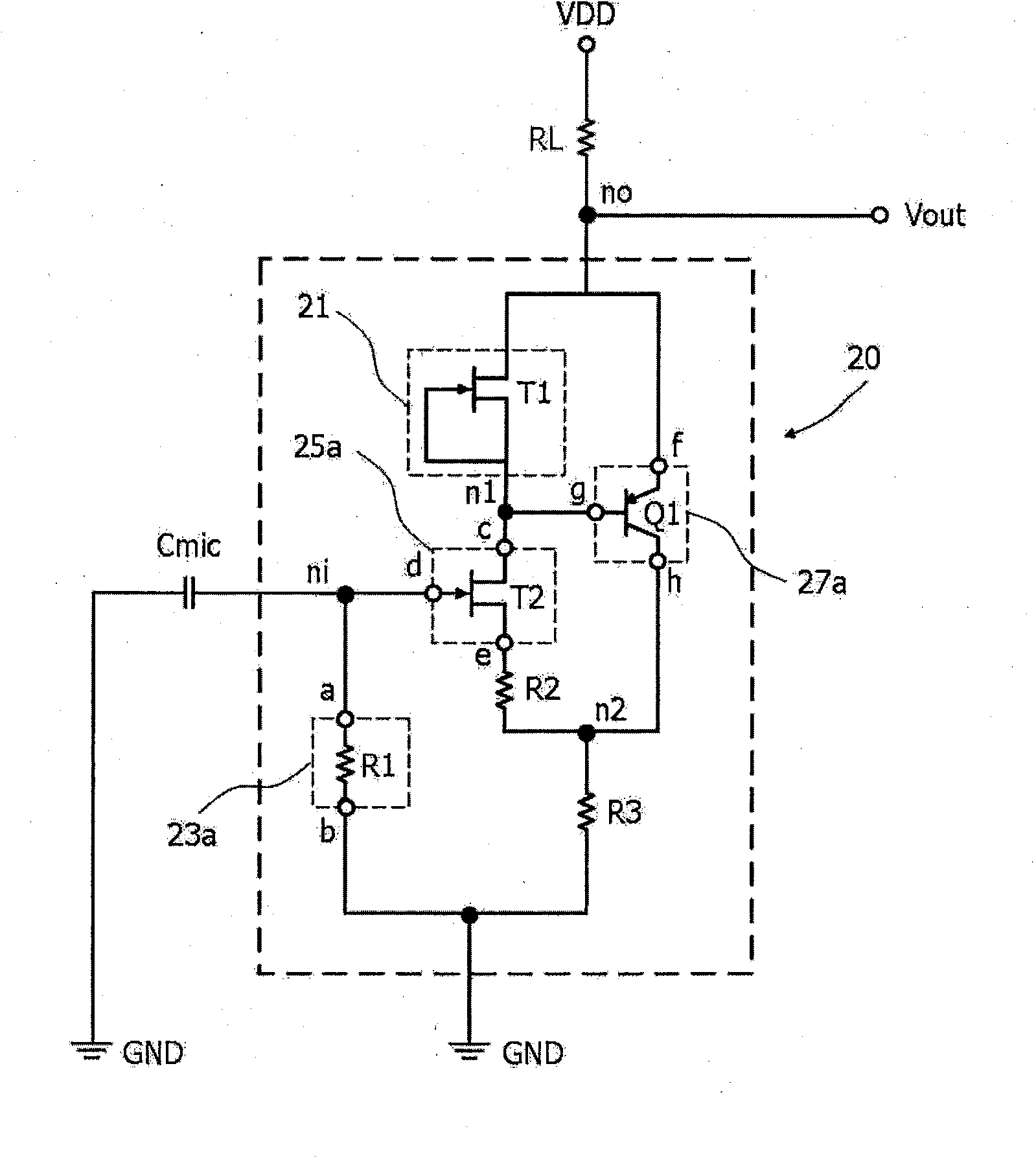
The present invention relates to a microphone amplifier, including a bias unit for providing an input signal reference potential between a signal input terminal and a ground terminal, a voltage-to-current conversion unit for amplifying the input signal, a constant current source for supplying constant current to the voltage-to-current conversion unit, and a current amplification unit for amplifying variation in current between the constant current source and the voltage-to-current conversion unit. The above-described present invention provides a highly trustworthy microphone amplifier, in which a low-noise characteristic junction field effect transistor and a low- noise characteristic bipolar transistor are combined together, thereby realizing high input impedance, high amplification gain and low current consumption.

Description

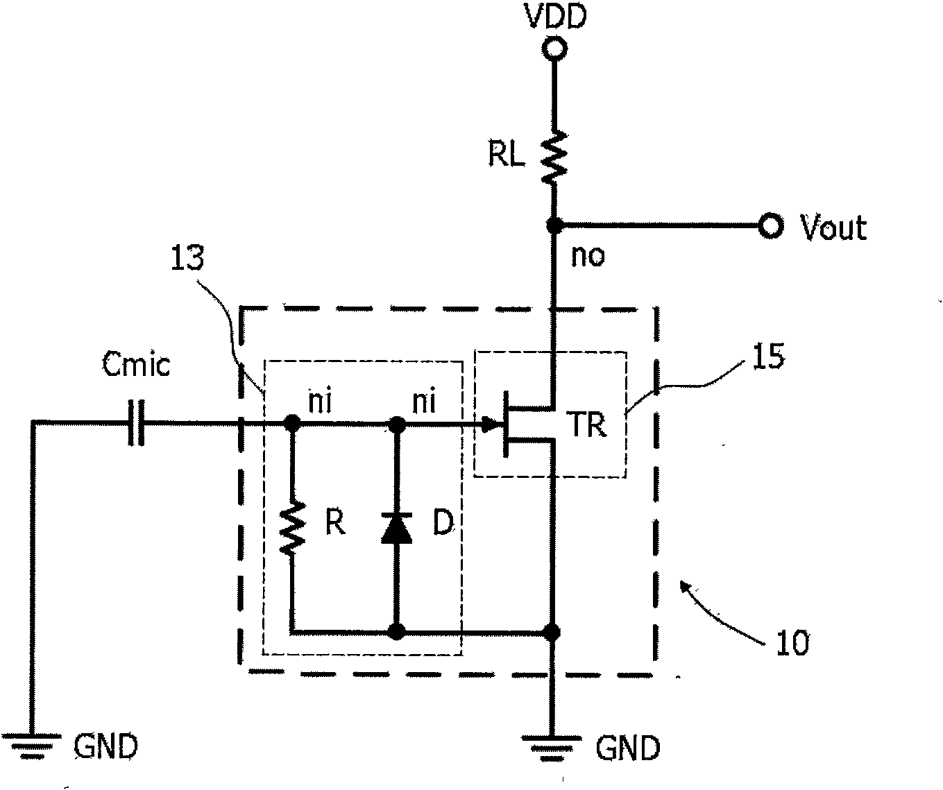
technical field [0001] The invention discloses a microphone. The invention uses a junction field effect transistor (JFET) and a bipolar transistor element to realize a microphone amplifier with high input impedance, high amplification gain and low current consumption. [0002] Microphone amplifiers are suitable for use with microphones that convert speech signals into electrical signals. Background technique [0003] figure 1 It is a circuit diagram of an existing capacitive microphone amplifier. The microphone amplifier 10 includes a single junction field effect transistor (JFET, 15 ) and a bias unit 13 that can provide the operating reference potential of the JFET 15 . [0004] The gate of the JFET 15 of the amplifier 10 is connected at a node (ni) to an electrostatic capacitor (Cmic) capable of generating an electric signal according to vibration of a voice signal. The other end of the capacitance (Cmic) is connected to the ground (GND) together with the source of the J...

Claims


Application Information

Patent Timeline
Patent Type & Authority Applications(China)
IPC IPC(8): H04R3/00
CPCH04R19/04H04R2410/00H04R3/00
Inventor 李振孝李揆弘申熙泉尹宪一
Owner RFSEMI TECH INC
Learn More