
A thermal decomposition treatment system of flammable waste and method for treating the waste using the system

一种处理系统、热分解的技术,应用在可燃性废弃物热分解处理系统及使用该系统的废弃物处理领域,能够解决空气污染、作业效率低、炉收缩变形等问题,达到能效优越、工程效率极大化、防止大气污染的效果

Inactive Publication Date: 2010-03-24
李锺镐
View PDF1 Cites 3 Cited by
  • Summary
  • Abstract
  • Description
  • Claims
  • Application Information

AI Technical Summary

Problems solved by technology

However, according to this method, since the thermal decomposition is completed without removing the air, there are still problems such as the generation of harmful gases containing harmful substances caused by oxidation and incomplete combustion.
[0009] For this reason, Korean Patent No. 10-0510818 discloses a method of performing thermal decomposition and carbonization processes in a vacuum state, but according to the above-mentioned known prior art, due to the expansion of superheated steam, it is necessary to remove the heat inside the heating furnace. Contaminated gas is discharged to the outside, so there are problems that air pollution cannot be solved, and there are also problems such as increased fuel costs due to repeated cooling and reheating
[0010] Moreover, on the equipment, in order to set up the internal structure, it is necessary for the staff to directly enter the interior of the device to perform related welding and other operations, but this can only be implemented on large-scale incineration devices, but cannot be implemented on small and medium-sized incineration devices
[0011] Moreover, according to the above-mentioned vacuum method, the time for forming a vacuum in the furnace by cooling is too long, the work efficiency is low, and problems such as shrinkage and deformation of the furnace itself also occur, so there are great limitations in practical use.
[0012] In addition, a rotary kiln method has been proposed in which the heating furnace is elongated in the horizontal direction, and the above heating furnace is rotated by a driving mechanism, and the waste is incinerated by external heating. However, this rotary kiln method It is not a vacuum method, so it cannot solve the problem of discharging harmful gases caused by combustion, and according to this method, a drive mechanism needs to be provided separately, so the structure and production are complicated, and the production cost increases. The rotation of a large-capacity heating furnace requires electricity and The fuel cost of external heating increases, it is not economical in terms of energy efficiency, and there is also a problem that it is difficult to remove debris, so there are also limitations in practicality

Method used


Image

  • A thermal decomposition treatment system of flammable waste and method for treating the waste using the system
  • A thermal decomposition treatment system of flammable waste and method for treating the waste using the system
  • A thermal decomposition treatment system of flammable waste and method for treating the waste using the system

Examples


Embodiment Construction

[0042] Preferred embodiments of the combustible waste thermal decomposition treatment system and the waste treatment method using the system according to the present invention will be described in detail below with reference to the accompanying drawings.

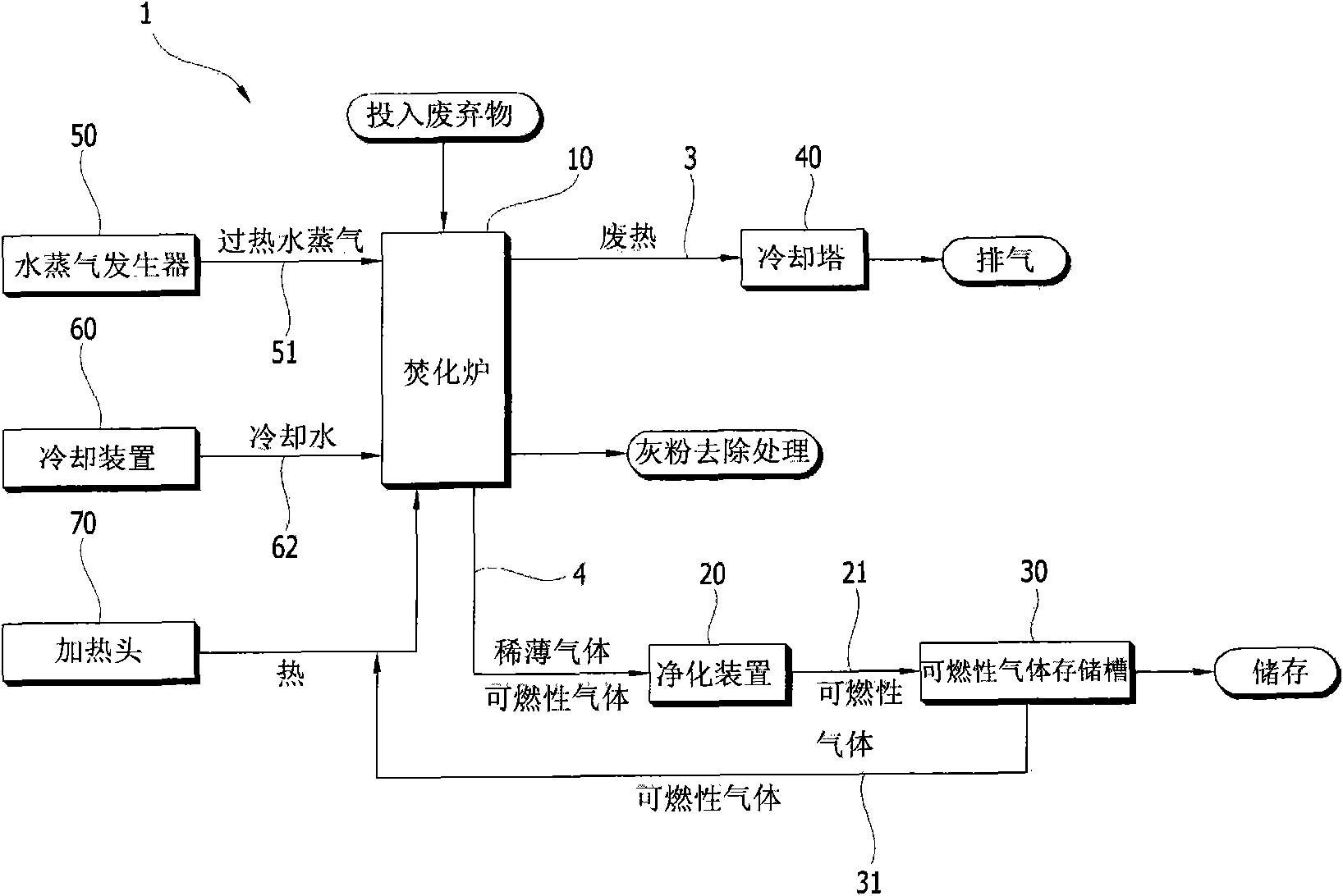
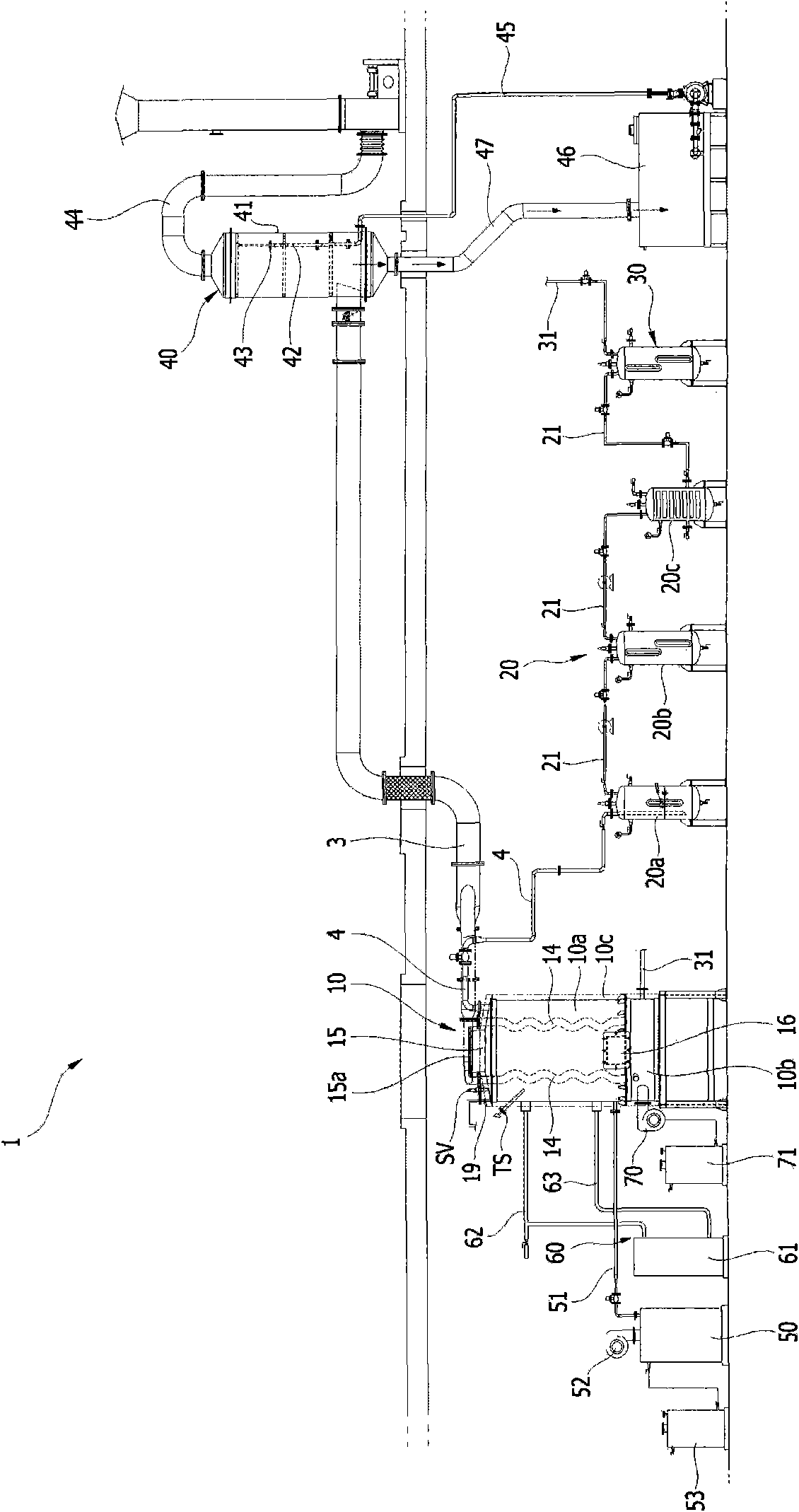
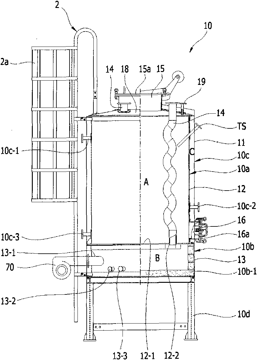
[0043] figure 1 To represent the brief treatment process diagram of the combustible waste pyrolysis treatment system of the present invention, figure 2 To represent the system structure diagram of the combustible waste pyrolysis treatment system of the present invention, image 3 , Figure 4 It is a structural diagram showing an incinerator suitable for the combustible waste pyrolysis treatment system of the present invention, and, Figure 5 , Figure 6 to indicate that it applies to image 3 , Figure 4 Front view of the heating tubes and pressure gauges and vacuum gauges.

[0044] As shown in the figure, the combustible waste thermal decomposition treatment system 1 according to the present invention mainly includes...


PUM


Abstract

The present invention relates to a system for treating flammable wastes and a method for treating the same, and more particularly, to a thermal decomposition treatment system of the flammable waste and a waste treatment method of the waste using the same through which the flammable waste inputted into a trash burner is shielded from air or gas and the waste is thermally decomposed and carbonated through a indirect heating by a heating tube for combustible gas to be extracted and recovered for a reuse without emitting contaminated gas, etc. The thermal decomposition treatment system according to the present invention includes a trash burner including a thermal decomposition chamber, a combustion chamber, and a cooling water chamber; a water vapor generator which is communicated to the thermal decomposition chamber through the water vapor supply tube and into which over heated water vapor is forced to be inputted; a cooling unit which is communicated to the cooling water chamber througha cooling water input tube and a cooling water discharging tube, and the cooling water is provided and circulated through this configuration; a purifier which is communicated to the thermal decomposition chamber through the gas discharging tube, and poisonous gases contained in rare gases and combustible gas are removed through this configuration; a combustible gas storage reservoir which is communicated to the purifier through a gas transfer tube and stores the purified combustible gas, and allows some of it to be inputted into the combustion chamber through a gas circulation tube; and a cooling tower which is communicated to a waste heat recovery tube connected to the heating tube and which collects high temperature air passed therethrough, and allows the high temperature air to be cooled and discharged to atmosphere.

Description

technical field [0001] The present invention relates to a system and method for treating various combustible wastes. More specifically, the combustible wastes put into the incinerator are set in a state of being isolated from air or gas, and heated by heating tubes. A combustible waste pyrolysis treatment system and a waste treatment method using the system can be used to extract and recover combustible gas for reuse by indirect heating such as pyrolysis and carbonization of the above-mentioned combustible waste. Background technique [0002] Currently, the disposal of combustible waste such as industrial waste sludge and household garbage is a social issue, and various proposals have been proposed for their effective disposal. [0003] Among the widely used methods of disposal of such combustible wastes are methods of minimizing the volume of the above-mentioned combustible wastes, burying, incinerating or throwing them into the sea. [0004] However, the methods of buryin...

Claims


Application Information

Patent Timeline
Patent Type & Authority Applications(China)
IPC IPC(8): F23G5/027
CPCF23J15/06F23G2207/102F23G5/46F23G5/50Y02E20/363Y02E20/346F23G5/0273F23G2207/101Y02E20/30Y02P80/15F23G5/027F23G7/06
Inventor 李锺镐
Owner 李锺镐
Learn More