Cold-mould vertical spraying and cleaning system

A cold and vertical technology, used in casting and forming equipment, metal processing equipment, manufacturing tools, etc., can solve the problems of large floor space, low relative efficiency, difficult manual control, etc., to save work space and large bearing capacity. , the effect of convenient operation

Active Publication Date: 2010-03-31
中国冶金科工股份有限公司
View PDF0 Cites 8 Cited by
  • Summary
  • Abstract
  • Description
  • Claims
  • Application Information

AI Technical Summary

Problems solved by technology

[0002] Existing mold cleaning methods include: 1) single-arm suspension horizontal pneumatic or electric motor cleaning methods, such as Figure 1a As shown, in this method, the casting mold A is placed horizontally on the cleaning site, and the casting mold is still. The cleaning wheel B is a single wheel in contact with the inner surface of the casting mold A, and its rotating tangential force drives the motor to make a circular motion along the inner wall of the casting mold. The method is simple in structure, but the efficiency is low and the pollution is serious; 2) the single-arm suspension type horizontal centrifugal electric motor cleaning method, such as Figure 1b As shown, this method uses the centrifugal force generated by the rotation of the motor to throw the friction block C radially and make a circular motion. This method has complex structure, low efficiency, and serious pollution; 3) Cantilever car cleaning system (such as Figure 1c As shown), casting mold A is placed horizontally on the special rotating mechanism D (paint cleaning machine) for circular motion, and the cantilever car E drives the single-arm motor to move axially in casting mold A. This method has a huge mechanism and is different from the corresponding spraying The system together constitutes a horizontal spraying and cleaning system, which is relatively inefficient, complex in mechanism and heavy in pollution
[0003] Existing mold spraying method comprises: 1) hand-held spray gun spraying method (as Figure 1d As shown), the hand-held spray gun F is used to spray from the end of one side of the stationary mold A along the circumferential direction, and at the same time, the axial direction is spirally pushed inward from the end. This method is relatively primitive, and the deviation of paint thickness and paint adhesion is relatively large; 2 ) Artificial rod spray gun spraying method (such as Figure 1e As shown), the nozzle is fixed on the round pipe rod to form the rod-type spray gun G, the manual push-pull rod-type spray gun G moves axially along the central axis of the mold A, and the mold A is placed horizontally on the special rotating mechanism D for circular motion , this method is suitable for occasions where the length of the mold is not too long, and it is difficult to control manually when the spray gun is long; 3) Cantilever car spraying method (such as Figure 1f As shown), casting mold A is placed horizontally on the special rotating mechanism D (paint spraying machine) for circular motion, and the cantilever vehicle E drives the single-arm spray gun G to move axially in casting mold A. This method can realize horizontal spraying Mechanical automatic spraying, but the mechanism is huge and complex, occupies a large area, and is seriously polluted. For very long mold spraying, the swing and vibration of the cantilever are unavoidable

Method used


Image

  • Cold-mould vertical spraying and cleaning system
  • Cold-mould vertical spraying and cleaning system
  • Cold-mould vertical spraying and cleaning system

Examples


Embodiment Construction

[0031] In order to have a clearer understanding of the technical features, purposes and effects of the present invention, the specific implementation manners of the present invention will now be described with reference to the accompanying drawings.

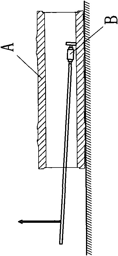
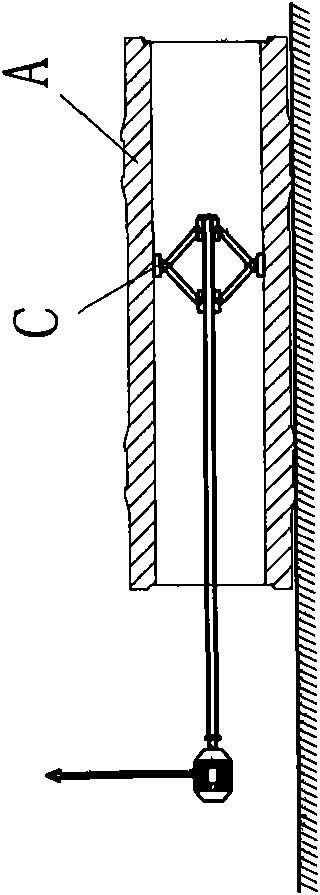
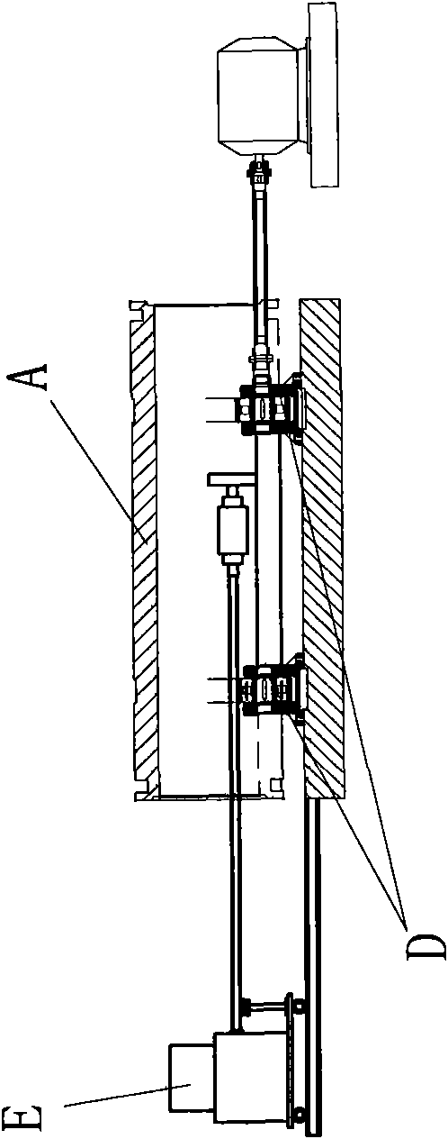
[0032] Such as figure 2 , image 3As shown, a cold type vertical spraying and cleaning system, the spraying and cleaning system includes a pit 8 capable of accommodating the cold type 9 vertically, and the bottom of the pit 8 is provided with a fixed support cold type 9 The bottom end drives the hollow rotating bracket 7 that rotates around the longitudinal axis of the cold type 9; the dust removal device 6 is arranged under the hollow rotating bracket 7; the operating vehicle 5 that can move along the pit is arranged on the top of the pit 8 , the operating vehicle 5 is provided with a vertically arranged hollow guide rod 4 that can move up and down, and the lower port of the hollow guide rod 4 is provided with an actuator; the...


PUM


Abstract

The invention relates to a cold-mould vertical spraying and cleaning system comprising a ground pit, a hollow rotating bracket, a dust remover, an operating vehicle, a hollow guide rod and an actuating mechanism, wherein the ground pit can contain a cold mould which is placed vertically; the hollow rotating bracket is arranged on the bottom of the ground pit and used for fixing and supporting thebottom end of the cold mould and driving the cold mould to rotate around the vertical shaft of the hollow rotating bracket; the dust remover is arranged below the hollow rotating bracket; the operating vehicle is arranged on the top of the ground pit and capable of moving along the ground pit; the hollow guide rod is vertically arranged on the operation vehicle and capable of moving up and down; and the actuating mechanism is arranged on the lower end port of the hollow guide rod. In the invention, the casting mould for spraying or cleaning is vertically arranged instead of being horizontallyarranged in a traditional way, and therefore, the occupation area of the casting mould is reduced by about 50% as compared with the traditional horizontal way. By adopting direct-current variable-speed hoisting equipment, the invention can automatically control according to different thickness requirements for the paints of the cold mould in different positions. The system has the advantages of simpler structure and more convenient operation; the system adopts the hollow rotating bracket to organically combine the rotation and the support of the cold mould and enhance the bearing capacity; andsince a passage is formed at the center of the hollow rotating bracket, the system can remove dust, thereby being beneficial to environmental protection.

Description

technical field [0001] The invention relates to a spraying and cleaning device, in particular to a casting mold or cold-type spraying and cleaning system in the fields of large static and centrifugal casting rolls, large centrifugal casting pipes and the like. Background technique [0002] Existing mold cleaning methods include: 1) single-arm suspension horizontal pneumatic or electric motor cleaning methods, such as Figure 1a As shown, in this method, the casting mold A is placed horizontally on the cleaning site, and the casting mold is still. The cleaning wheel B is a single wheel in contact with the inner surface of the casting mold A, and its rotating tangential force drives the motor to make a circular motion along the inner wall of the casting mold. The method is simple in structure, but the efficiency is low and the pollution is serious; 2) the single-arm suspension type horizontal centrifugal electric motor cleaning method, such as Figure 1b As shown, this method ...

Claims


Application Information

Patent Timeline
Patent Type & Authority Applications(China)
IPC IPC(8): B22C23/02B22C23/00
Inventor 周守航王永涛黄衍林韩庆礼张西鹏刘艳
Owner 中国冶金科工股份有限公司
Why Eureka
Try Eureka