High-reliability precise driving device
A driving device and power device technology, which is applied to transmission devices, differential transmission devices, electromechanical transmission devices, etc., can solve the problems of shortened service life of equipment, poor manufacturability, and increased operating noise of the mechanism, and achieves simple and convenient manufacturing and processing technology. Low manufacturing cost and the effect of ensuring the coaxiality of installation
- Summary
- Abstract
- Description
- Claims
- Application Information
AI Technical Summary
Problems solved by technology
Method used
Image

Examples
Embodiment Construction
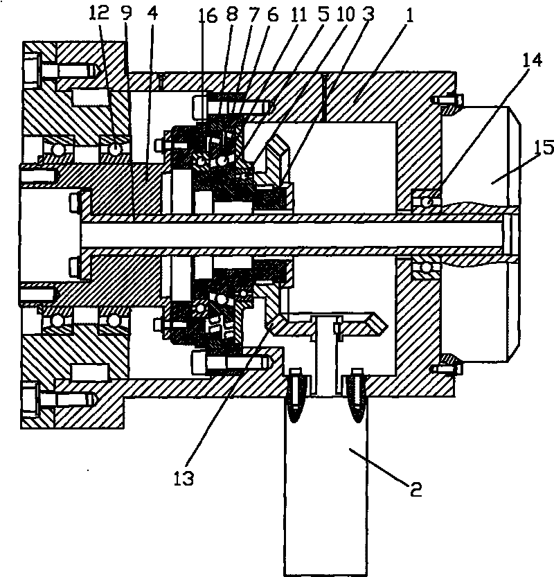
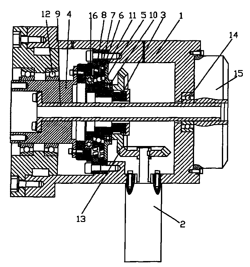
[0019] figure 1 It is a structural schematic diagram of the present invention, as shown in the figure: the high-reliability precision driving device of this embodiment includes a casing 1, a power device 2 and a transmission mechanism, and the power output end of the power device is in transmission cooperation with the power input end of the transmission mechanism , the transmission mechanism is a reducer with less tooth difference, including a power input shaft 3 and a power output shaft 4, and an eccentric sleeve 5 is arranged on the power input shaft 3. In this embodiment, the power input shaft 3 and the eccentric sleeve 5 are integrally manufactured The outer circle of the eccentric sleeve 5 is rotated and fitted with a double-connected external gear 6, and the housing 1 is concentrically fixed with the power input shaft 3. The fixed internal gear 7 is fixed, and the power output shaft 4 is driven and matched with the power input shaft in the circumferential direction. 3 C...
PUM
 Abstract
Description
Claims
Application Information