Light and thin composite hot water heating floor

A hot water heating and composite technology, applied in hot water central heating systems, heating methods, household heating and other directions, can solve the problems of low pressure resistance and deformation resistance of thermal insulation materials, inability to meet user requirements, and high water quality requirements. Improve the mechanical and thermal properties such as compression resistance, appropriate thermal conductivity, and simplify construction and maintenance.

Inactive Publication Date: 2010-04-28
北京建筑工程学院 +1
View PDF0 Cites 10 Cited by
  • Summary
  • Abstract
  • Description
  • Claims
  • Application Information

AI Technical Summary

Problems solved by technology

[0005] The thermal insulation structures adopted in the above three dry methods all use polystyrene foam boards or extruded foam plastic boards alone. The main problems are: 1) This type of thermal insulation material has low pressure resistance and deformation resistance. If no corresponding measures are taken Easy to plastically deform when the thickness is large
The insulation thickness increases with the increase of the heating pipe diameter, but the pipe diameter is too small, such as the integrated dry floor, which requires high water quality, the pipes are easy to block, the system resistance is large, and the energy consumption is large
2) Composite wood flooring is more suitable for the opposite surface layer, but when the surface layer is ceramic tile, stone, etc., it needs to be changed to wet construction, so that when the same room uses different surface layers, the floor will have a height difference, which cannot meet user requirements

Method used


Image

  • Light and thin composite hot water heating floor
  • Light and thin composite hot water heating floor
  • Light and thin composite hot water heating floor

Examples


Embodiment Construction

[0018] The mechanism, specific structure and implementation of the present invention will be further described below in conjunction with the accompanying drawings.

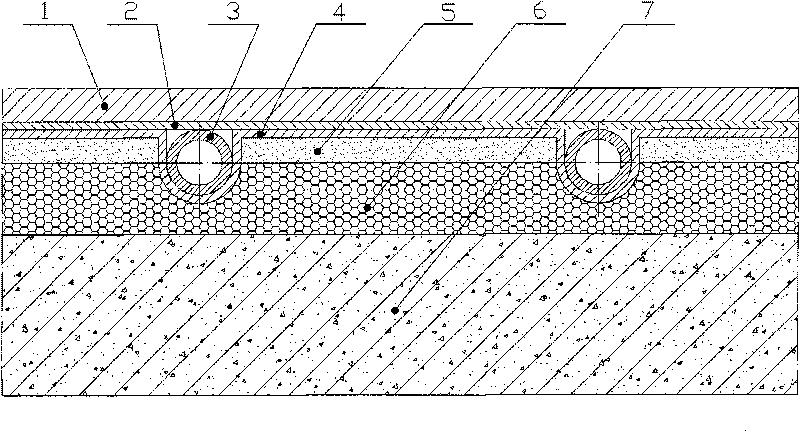
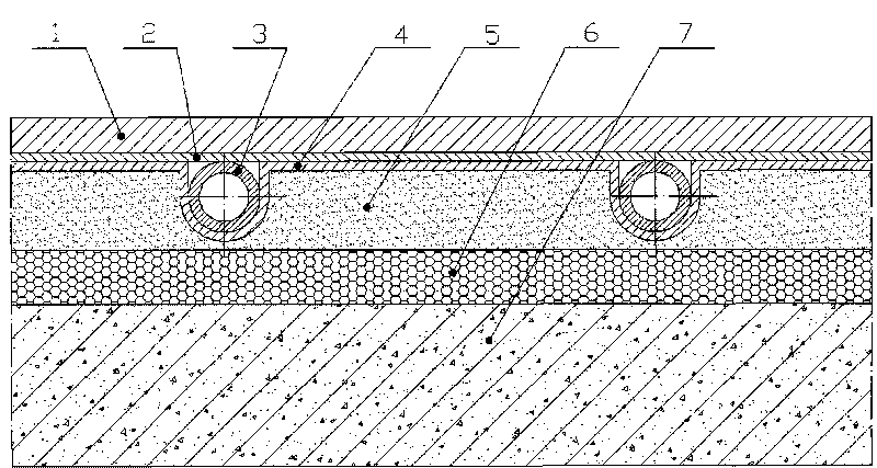
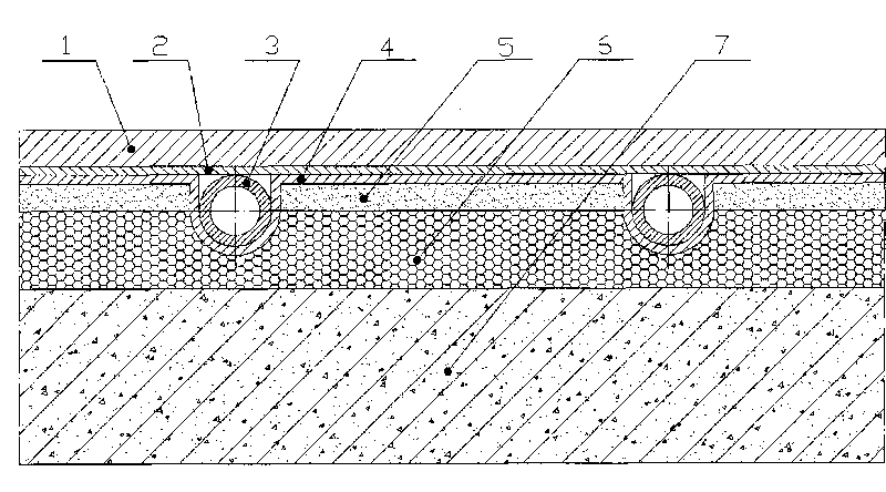
[0019] figure 1 The structural diagram of the first embodiment provided by the present invention, the floor includes a ground decoration layer 1, an upper metal heat conduction layer 2, a heating pipe 3, a lower metal heat conduction layer 4, a silicon-calcium board 5, an insulation layer 6, and a floor slab 7; Pipe grooves are set in the silicon-calcium board and the insulation layer, and the lower metal heat-conducting layer and the surface of the pipe groove are laid next to each other, and prefabricated with the silicon-calcium board and the insulation layer to form a prefabricated composite board with pipe grooves. The heating tube 3 is placed on the lower metal heat-conducting layer in the pipe groove; the upper metal heat-conducting layer is laid horizontally on the heating tube and the lower metal heat-con...


PUM


Abstract

The invention relates to a light and thin composite hot water heating floor which belongs to the technical field of heating. The floor structure comprises a ground decoration layer, an upper-layer metal heat-conducting layer, a heating pipe, a lower-layer metal heat-conducting layer, a calcium silicate board, a thermal insulation layer and a floor plate. The calcium silicate board can enhance pressure resistance, anti-aging deformation property and durability of the floor and enhance the heat conductivity in the heating pipe; a composite heat-conducting structure consists of the upper-layer metal heat-conducting layer, the heating layer coated with a metal film on the outer surface, the lower-layer metal heat-conducting layer and the calcium silicate board can effectively enhance the heat transfer of the floor structure layer, lead the ground temperature to be even, reduce the impacts of temperature stress and avoid the deformation and the damage of the floor; and the composite heat-conducting structure is combined with the thermal insulation layer therebelow, thereby being conductive to mounting and leveling and reducing the downward heat loss. The floor structure can simultaneously improve mechanical and thermal performances, be applicable to a variety of surface layers of wood floors, cement, tiles, stones and the like of newly built and existing buildings, solve the limitations of dry floor applications, avoid the shortcomings of the wet floor structure and realize strong adaptability, simple construction and convenient maintenance.

Description

technical field [0001] The invention relates to a hot water heating floor structure, which belongs to the technical field of building heating. Background technique [0002] Low-temperature hot water ground radiation heating uses hot water with a temperature not higher than 60°C as the heat medium, circulates in the heating pipe, heats the floor, and dissipates heat to the room through the ground through radiation heat exchange and convection heat exchange. Compared with the traditional convection heating method, the low-temperature hot water floor heating has high comfort, saves energy, and can utilize low-grade heat energy. At the same time, it is conducive to the implementation of household heat metering and convenient building decoration. The floor heating method can better adapt to the needs of the development of modern comfortable and energy-saving building technology. It is a comfortable and energy-saving heating method with broad development and application prospects...

Claims


Application Information

Patent Timeline
Patent Type & Authority Applications(China)
IPC IPC(8): F24D3/14E04F15/00
Inventor 王随林谢文新潘树源闫全英
Owner 北京建筑工程学院
Why Eureka
Try Eureka