Device for producing triangular fiber grating
A fiber grating and manufacturing device technology, which is applied in cladding optical fiber, optical waveguide light guide, photoplate process of pattern surface, etc., can solve the limited Bragg wavelength adjustability, mechanical stability and high spatial coherence of the writing beam , Difficulty in adjusting the writing device, etc., to achieve the effect of easy wavelength adjustment, low cost, and simple structure
- Summary
- Abstract
- Description
- Claims
- Application Information
AI Technical Summary
Problems solved by technology
Method used
Image
Examples
Embodiment 1
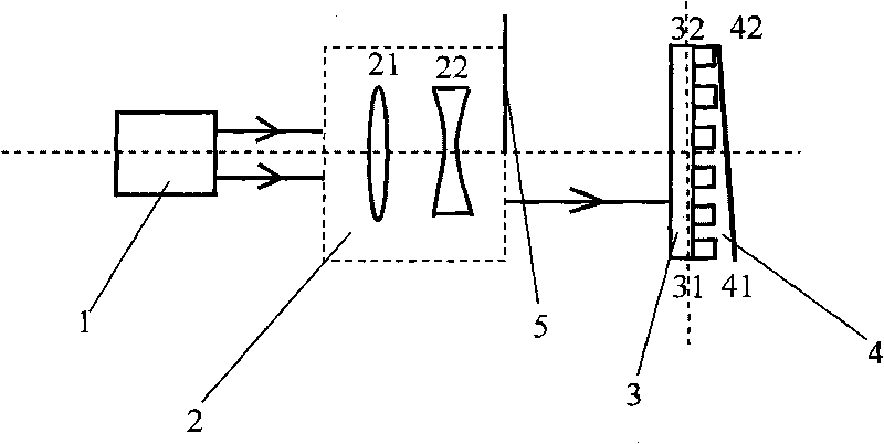
[0020] This embodiment combines the attached figure 1 Further explanation.
[0021] A device for manufacturing a triangular fiber grating that uses a converging lens and a diverging lens to form a speed expansion system, such as figure 1 shown.
[0022] The manufacturing device includes: an excimer laser 1 , a speed expansion system 2 composed of a first converging lens 21 and a first diverging lens 22 , a phase mask 3 , an optical fiber 4 , and a black cloth 5 .
[0023] The excimer laser 1 is used as the writing light source, and the lenses in the expansion system 2 are placed in the order of the first converging lens 21 and the first diverging lens 22. The expansion system 2 and the phase mask 3 are placed perpendicular to the main optical axis. And make the center of the phase mask 3 just on the main optical axis, place the 42 end of the optical fiber close to the 32 end of the phase mask, and make the optical fiber 4 tilt an angle of 1° relative to the phase mask 3 . T...
Embodiment 2
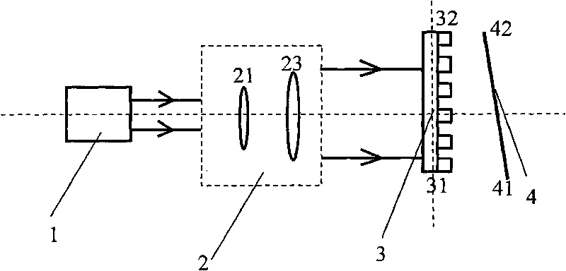
[0027] This embodiment combines the attached figure 2 Further explanation.
[0028] A device for manufacturing a triangular fiber grating that uses two converging lenses to form a speed-expanding system, such as figure 2 shown.
[0029] The fabrication device includes: an excimer laser 1 , a speed expansion system 2 composed of a first converging lens 21 and a second converging lens 23 , a phase mask 3 , and an optical fiber 4 .
[0030] The excimer laser 1 is used as a writing light source, and the lenses in the expansion system 2 are placed in the order of the first converging lens 21 and the second converging lens 23, the expansion system 2 and the phase mask 3 are placed perpendicular to the main optical axis, and The center of the phase mask 3 is upwardly deviated from the main optical axis by 5mm, the distance between the end 42 of the optical fiber and the end 32 of the phase mask is 5mm, and the optical fiber 4 is inclined at an angle of 15° relative to the phase m...
Embodiment 3
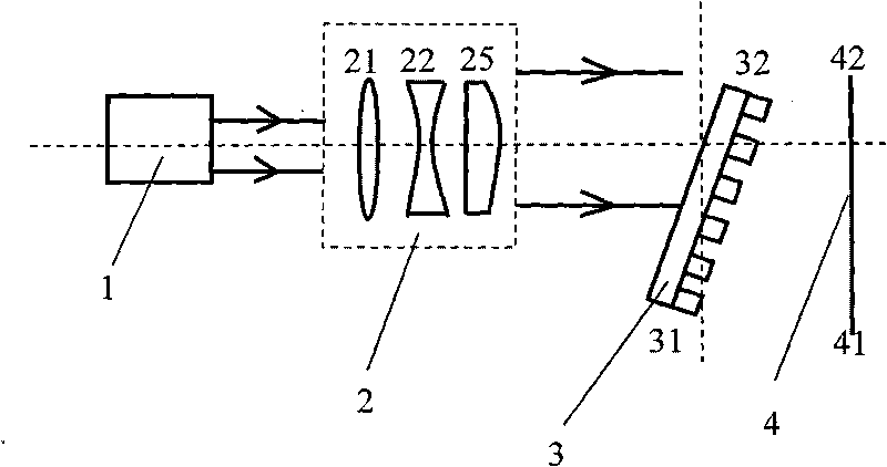
[0034] This embodiment combines the attached image 3 Further explanation.
[0035] A device for manufacturing a triangular fiber grating that uses a converging lens, a diverging lens, and a compensating lens to form a speed expansion system, such as image 3 shown.
[0036] The manufacturing device includes: an excimer laser 1 , a speed expansion system 2 composed of a first converging lens 21 , a first diverging lens 22 and a compensating lens 25 , a phase mask 3 , and an optical fiber 4 .
[0037] The excimer laser 1 is used as the writing light source, and the arrangement order of the lenses in the speed expansion system 2 is the first converging lens 21, the first divergence lens 22, and the compensation lens 25. The speed expansion system 2 is placed perpendicular to the main optical axis, and the phase mask The template 3 forms an angle of 30° with the main optical axis, and the center of the phase mask 3 deviates downward from the main optical axis by 50mm, the optic...
PUM
| Property | Measurement | Unit |
|---|---|---|
| Wavelength | aaaaa | aaaaa |
| Wavelength | aaaaa | aaaaa |
| Wavelength | aaaaa | aaaaa |
Abstract
Description
Claims
Application Information
 - R&D
- Intellectual Property
- Life Sciences
- Materials
- Tech Scout
- Unparalleled Data Quality
- Higher Quality Content
- 60% Fewer Hallucinations
Browse by: Latest US Patents, China's latest patents, Technical Efficacy Thesaurus, Application Domain, Technology Topic, Popular Technical Reports.
© 2025 PatSnap. All rights reserved.Legal|Privacy policy|Modern Slavery Act Transparency Statement|Sitemap|About US| Contact US: help@patsnap.com


