
Transformer-free inverter

A technology of transformers and inverters, applied in the field of transformerless inverters, which can solve the problem of increasing the step-up ratio of the front-stage DC/DC boost circuit and the difficulty of design, the inability to improve the power generation quality and efficiency of the inverter, and increasing the front-end The number of series-connected DC input sources and other issues can be solved to achieve the effects of reducing copper loss and magnetic loss, simple structure, and reduced volume

Inactive Publication Date: 2010-05-12
ZHEJIANG UNIV
View PDF0 Cites 35 Cited by
  • Summary
  • Abstract
  • Description
  • Claims
  • Application Information

AI Technical Summary

Problems solved by technology

[0005] At present, full-bridge inverters and half-bridge inverters with bipolar modulation are generally used to solve the common-mode current problem. However, this type of inverter structure can only achieve two-level modulation of the output voltage, resulting in output current The ripple is large, and the volume of the output filter inductor increases accordingly, so that the quality and efficiency of the inverter power generation cannot be improved. The half-bridge mid-point clamped inverter structure can eliminate the leakage current to the ground and realize the three-dimensional output voltage at the same time. Level modulation, but this structure requires that the DC side input voltage is twice that of the full-bridge inverter, correspondingly increasing the number of DC input sources in series in the previous stage or increasing the boost of the DC / DC boost circuit in the previous stage Proportion and design difficulty.

Method used


Image

  • Transformer-free inverter
  • Transformer-free inverter
  • Transformer-free inverter

Examples


Embodiment Construction

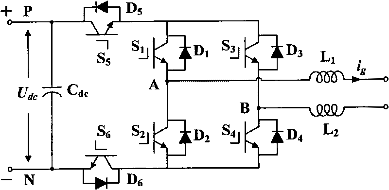
[0018] See attached figure 1 , the transformerless inverter of the present invention includes an input capacitor C dc , six power switch tubes, six anti-parallel diodes, two filter inductors L 1 and L 2 ; The first power switch tube S 1 , the first anti-parallel diode D 1 , the second power switch tube S 2 , the second antiparallel diode D 2 , the third power switch tube S 3 , the third anti-parallel diode D 3 and the fourth power switch S 4 , the fourth anti-parallel diode D 4 together constitute a full-bridge structure circuit, the fifth power switch tube S 5 The drain, input capacitance C dc The positive terminal of the input DC terminal is connected to the positive terminal of the input DC terminal, and the fifth power switch tube S 5 source of the first power switch S 1 The drain of the third power switch S 3 connected to the drain of the first power switch S 1 source of the second power switch S 2 The drain with the first filter inductor L 1 Connected to ...


PUM


Abstract

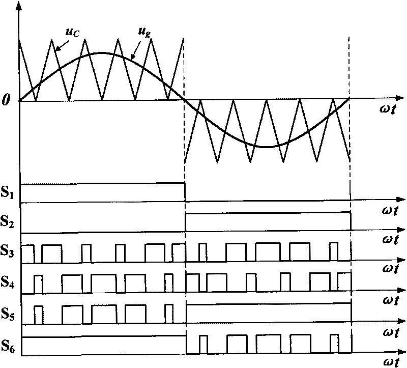
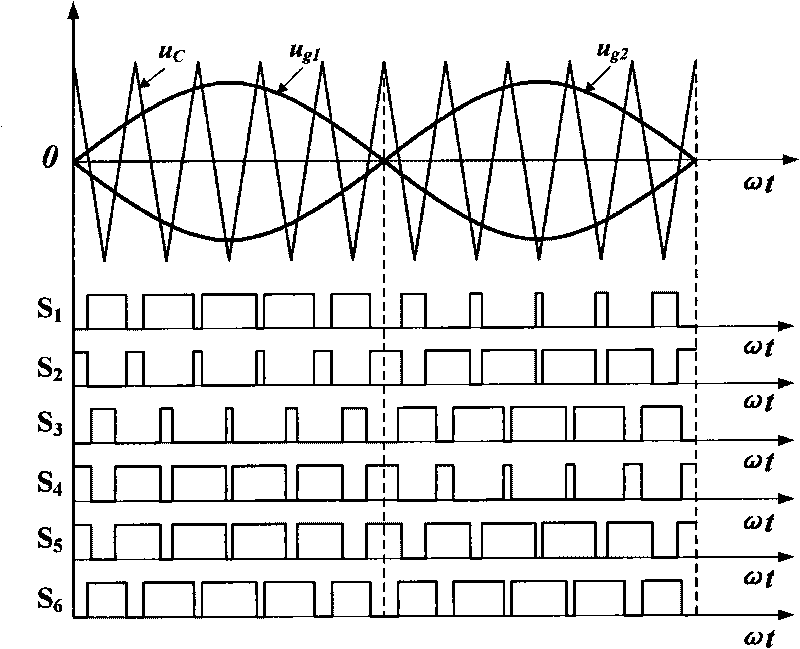
The invention discloses a transformer-free inverter, which comprises an input capacitor, six power switching tubes, six anti-parallel diodes and two filter inductors. The switching motion is performed by using the cooperation of the six power switching tubes and the anti-parallel diodes thereof, and then when the output voltage of the inverter has zero level, the output alternating current side and the input direct current side of the inverter are in a decoupling state so as to ensure that the common mode voltage of the inverter is kept constant when the output voltage of the inverter realizes three-voltage modulation and further fully eliminate the common mode current; the switching voltage on the power switching tubes is changed to be half of the direct current input voltage, so the switching loss of the power switching tubes is reduced; and the output current ripple wave of the inverter is further reduced through frequency doubling pulse width modulation, the output electrical energy quality of the inverter is improved, and the volumes of the filter inductors are reduced so as to reduce the copper loss and magnetic loss generated on the filter inductors.

Description

technical field [0001] The invention relates to an inverter in the field of DC-AC converters of power electronics technology, in particular to a transformerless inverter. Background technique [0002] Inverter refers to a power electronic converter that converts DC power into AC power through the opening and closing of semiconductor power switching devices. Its function is to convert the power quality obtained from batteries, solar cells, fuel cells, etc. The poorer DC raw power is converted into AC power with higher power quality that can meet the voltage and frequency requirements of the user's load. As the world's energy shortage and environmental pollution become increasingly serious, energy and the environment have become one of the most important issues facing mankind in the 21st century. The development and application of clean and renewable energy has attracted more and more attention from countries all over the world. . A large number of renewable energy sources a...

Claims


Application Information

Patent Timeline
IPC IPC(8): H02M7/5395
CPCY02E10/563H02J3/383H02M7/5387H02M2001/123H02J2300/24H02J3/381Y02E10/56H02M1/123
Inventor 何湘宁杨波
Owner ZHEJIANG UNIV
Learn More