
Dispersion compensation fiber and module thereof

A dispersion compensation fiber and dispersion compensation technology are applied in cladding fiber, multi-layer core/cladding fiber, electromagnetic wave transmission system, etc., which can solve the problem that the performance of dispersion compensation fiber and its modules cannot be fully evaluated, and the performance of G. The basic conditions of 652 dispersion compensation fiber, the fiber performance cannot meet the high performance and small size of the module, etc., to achieve the effect of miniaturization, improved signal quality, and low bending loss

Active Publication Date: 2012-08-15
YANGTZE OPTICAL FIBRE & CABLE CO LTD
View PDF4 Cites 0 Cited by
  • Summary
  • Abstract
  • Description
  • Claims
  • Application Information

AI Technical Summary

Problems solved by technology

US Patent 5361319 introduces a general refractive index profile for dispersion compensating optical fiber, but its attenuation (less than 1dB / km) and dispersion (less than -20ps / nm / km) indicators cannot meet the current application of communication transmission, and its quality factor is only 120ps / nm / km cannot meet the insertion loss requirements of current modules
Chinese patent CN1629667A describes a dispersion compensating fiber and its module, but this patent does not involve key indicators such as quality factor and insertion loss, and cannot fully evaluate the performance of the dispersion compensating fiber and its module, and cannot realize the miniaturization of the module
Chinese patent CN03125339.3 describes a high-performance dispersion compensation fiber, including 5 core layers, and the quality factor of the fiber at 1545nm reaches 350ps / nm / dB, which can meet the requirements of conventional dispersion compensation modules, but not Market Dispersion Compensation Module Requirements for High Performance and Small Size
Chinese patent CN200810246343.0 describes a dispersion compensating optical fiber with a high dispersion coefficient. The negative dispersion coefficient reaches -200ps / nm / km or lower at a wavelength of 1550nm, and the figure of merit (FOM) reaches 400ps / nm / dB, which has a high performance; but its RDS at 1550nm wavelength is equal to or greater than 0.018nm -1 , does not meet the basic conditions of G.652 dispersion compensation fiber, and cannot be used to make G.652 dispersion compensation modules
However, with the development of high-speed and large-capacity long-distance transmission communication systems, the market has put forward new requirements for dispersion compensation optical fiber technology, and the performance of existing optical fibers cannot meet the requirements of high performance and small size of modules

Method used


Image

  • Dispersion compensation fiber and module thereof
  • Dispersion compensation fiber and module thereof
  • Dispersion compensation fiber and module thereof

Examples


Embodiment Construction

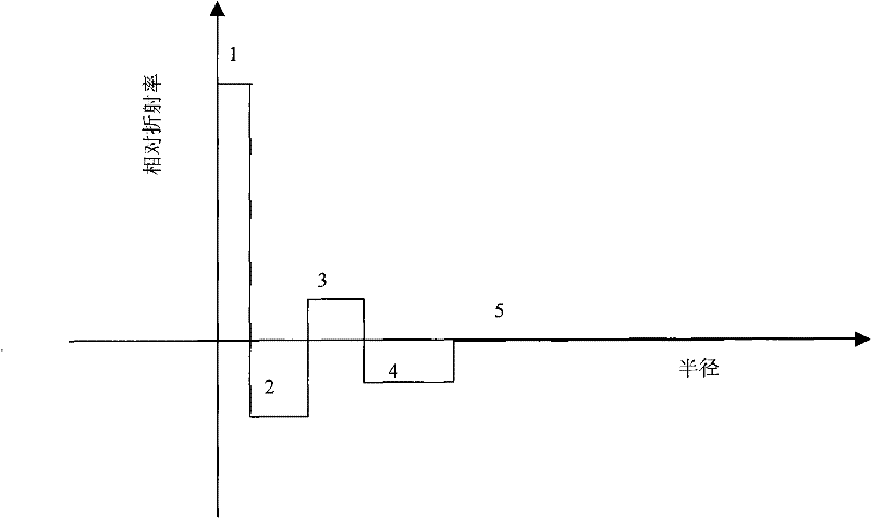
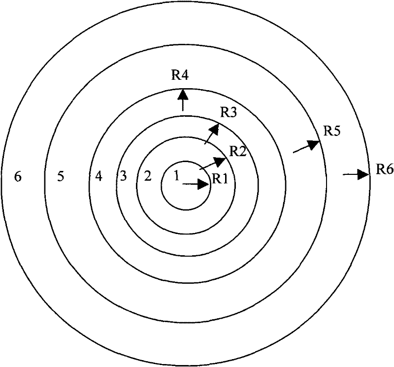
[0036] The optical fiber in the present invention has the same figure 1 With similar refractive index profile structures, optical fibers with different performance parameters can be obtained by changing the parameters of each layer of the refractive index profile structure. Embodiments of the present invention will be further described below in conjunction with the accompanying drawings.

[0037] In the first embodiment, the core rod of the optical fiber preform is manufactured by PCVD process, and a pure silica glass layer or a silica glass layer doped with germanium or fluorine is deposited on the inner wall of a high-purity silica glass substrate tube with an outer diameter of 28 mm. Then, the deposited quartz glass tube was melted and shrunk into a solid quartz glass core rod with a diameter of 20 mm. Then put the core rod into a quartz glass casing with an outer diameter of 60mm, enter a high-temperature furnace to melt the two into a solid quartz glass rod, and obtain a...


PUM

PropertyMeasurementUnit
diameteraaaaaaaaaa
diameteraaaaaaaaaa
lengthaaaaaaaaaa

Abstract

The invention relates to a dispersion compensation fiber for carrying out dispersion compensation at a C waveband and a module thereof. The structure of the dispersion compensation fiber comprises a fiber layer and a cladding and a sunken cladding, and an annular lading, a matching lading and a pure quartz cladding coat outside the fiber core in sequence, wherein the relationship that delta 1 percent>delta 3 percent>delta 4 percent>delta 5 percent>2 percent is satisfied, the difference range of relative index of refraction comprises the following sequence: delta 1 percent is 1.5 percent-2.0 percent, delta 2 percent is -0.7 percent to -0.5 percent, delta 3 percent is 0.4 percent-0.6 percent, delta 4 percent is -0.15 percent to -0.05 percent and delta 5 percent is 0; and the radius range ofthe fiber core and various claddings from R1 to R5 comprises the following in sequence: 1.4-1.6 micrometers, 4.3-4.8 micrometers, 6.8-7.8 micrometers, 10-15 micrometers and 38-63 micrometers. The dispersion compensation fiber has high negative dispersion and negative dispersion gradient at an optical communication window of C waveband, so an optical communication system working at C waveband window is easy to update, optical fibers can more easily insert into a communication link to meet the transmission requirements of high-speed high-capacity system and the miniaturization of the dispersioncompensation module can be more easily realized.

Description

technical field [0001] The invention relates to a dispersion compensating optical fiber working in the C-band (1530nm-1565nm band) optical communication window. The optical fiber can be used for dispersion and dispersion slope compensation of standard single-mode optical fibers (G.652, ITU-T standard). Its characteristics It has a higher quality factor, low attenuation coefficient and PMD coefficient, and has a small geometric size. The optical fiber can not only meet the requirements of conventional dispersion compensation modules, but also be suitable for making miniaturized dispersion compensation modules. Background technique [0002] With the widespread adoption of standard single-mode fiber DWDM systems and the development of high-speed, long-distance, non-relay and dense channels, wavelength division multiplexing transmission technology has developed rapidly, expanding the working wavelength band and increasing wavelength diversity will be develop rapidly. [0003] ...

Claims


Application Information

Patent Timeline
Patent Type & Authority Patents(China)
IPC IPC(8): G02B6/036H04B10/12H04B10/2525
Inventor 罗杰曹蓓蓓
Owner YANGTZE OPTICAL FIBRE & CABLE CO LTD
Learn More