Spiral rotating bed

A rotating bed, spiral technology, applied in chemical/physical/physical-chemical fixed reactors, dissolution, chemical methods of reacting liquids and gaseous media, etc., can solve the problem of increased energy consumption, no suction, and large resistance and other problems, to achieve the effect of small footprint, not easy to crust, and simple structure

Active Publication Date: 2011-09-21
CHINA PETROLEUM & CHEM CORP +1
View PDF17 Cites 3 Cited by
  • Summary
  • Abstract
  • Description
  • Claims
  • Application Information

AI Technical Summary

Problems solved by technology

The shortcomings of the above-mentioned high-gravity field rotating bed are that the gas phase resistance is large, the contact path of the gas-liquid two-phase is relatively short, and the surface renewal rate of the droplets is slow, which is not conducive to further improving the mass transfer process.
CN2581060Y discloses a rotating bed high-gravity multiphase reactor, which adopts a spiral channel type rotating bed. The spiral channel is an Archimedes spiral in the radial direction and a through channel in the axial direction. The rotating bed of this structure can obtain Long gas-liquid two-phase contact path, but still has the disadvantages of high resistance and no suction capacity
At the same time, due to the suction effect of the impeller, there will be phenomena such as gas phase bias flow and liquid phase entrainment.
In some fields, such as the field of flue gas purification treatment, due to the low gas phase pressure, the treatment equipment with obvious pressure drop cannot be applied, and the gas volume is large, and the energy consumption will be greatly increased if the gas delivery device is added.
Therefore, when above-mentioned existing high-gravity rotating bed is used for these fields, be subjected to certain restriction

Method used


Image

  • Spiral rotating bed
  • Spiral rotating bed
  • Spiral rotating bed

Examples


Embodiment Construction

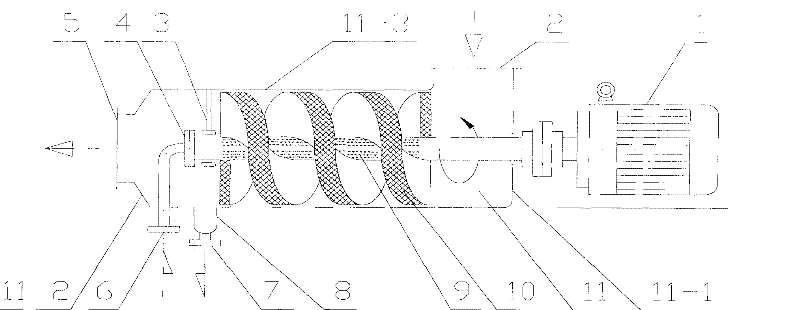
[0013] The present invention will be described in further detail below in conjunction with the accompanying drawings. Such as figure 1 , 2 , 3, the spiral rotating bed of the present invention consists of a spiral bed 10, a liquid phase distribution pipe 9, a shell 11, a support assembly 3, a gas phase inlet 2, a gas phase outlet 5, a liquid inlet 6, a rotary joint 4, a collection Liquid tank 8, liquid phase outlet 7 and motor 1 constitute.

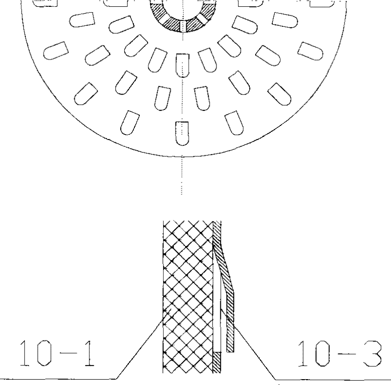
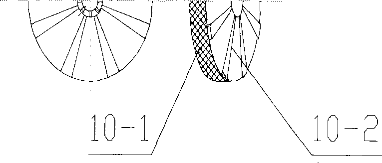
[0014] The spiral bed 10 is made of porous materials such as several layers of screens 10-1; a thin plate 10-3 is attached to the windward side of the rotating bed, or several evenly distributed strip plates 10-2 are attached; the method of attaching thin plates is adopted At the same time, the board is provided with several tongue-shaped slots or I-shaped slots, and the slots are distributed in the shape of fish scales; the slots are stamped, the tongue-shaped plate is raised, the height of the protrusion is 1-2mm, and the opening rate...


PUM


Abstract

The invention discloses a spiral rotating bed, comprising a spiral bed layer, a liquid-phase distribution pipe, a shell, a gas-phase inlet, a gas-phase outlet, a liquid-phase inlet, a liquid-phase outlet, and the like, wherein the spiral bed layer is made of porous materials and forms a spiral shape on the axial direction; the liquid-phase distribution pipe is arranged in the axial center of the spiral bed layer and communicated with the liquid-phase inlet; the gas-phase inlet and the gas-phase outlet are arranged at two ends of the shell, and the liquid-phase outlet is arranged at the bottomof the shell. The spiral rotating bed is suitable for gas-liquid mass transfer and reaction, especially the gas-liquid mass transfer and reaction for removing harmful ingredients in gas phase by utilizing liquid phase and with larger gas-liquid. The device has simple structure, small size, high mass transfer efficiency and low pressure drop, can obtain longer gas-liquid two-phase contact paths, realizes forced updating on the surface of droplet surface, and is beneficial to the gas-liquid mass transfer and reaction.

Description

technical field [0001] The invention relates to a helical rotating bed, in particular to a device which utilizes a high-speed rotating helical bed to complete gas-liquid mass transfer and reaction in a state of supergravity. Background technique [0002] The mass transfer and reaction equipment of the high gravity field rotating bed is a new type of chemical unit equipment developed in the early 1980s. Compared with the traditional technology, the high-gravity field rotating bed mass transfer equipment has the characteristics of high mass transfer intensity, small equipment size, short material residence time, low liquid holding capacity, and no flooding. [0003] Usually, the high-gravity field rotary bed equipment is composed of a casing, a rotor (reaction bed) and a motor. The rotor is a porous medium with the properties of a filler, where the material undergoes mass transfer and reaction. The gas phase needs to be transported by a fan, especially when the gas-liquid cou...

Claims


Application Information

Patent Timeline
Patent Type & Authority Patents(China)
IPC IPC(8): B01D3/30B01F3/04B01J19/18B01J10/00
Inventor 彭德强王丽君唐本义李建军范纯杰齐慧敏
Owner CHINA PETROLEUM & CHEM CORP
Why Eureka
Try Eureka