Method for producing clean fuels through low-cost hydrogenation

A technology for hydrogenation products and hydrotreating, applied in refining to remove heteroatoms, etc., can solve problems such as reducing reaction efficiency and failing to solve the removal of harmful impurities, reducing temperature rise, maintaining activity stability, and operating flexibility. Effect

Inactive Publication Date: 2010-06-09
CHINA PETROLEUM & CHEM CORP +1
View PDF7 Cites 46 Cited by
  • Summary
  • Abstract
  • Description
  • Claims
  • Application Information

AI Technical Summary

Problems solved by technology

[0012] U.S. Patents US6213835, US6428686, etc. disclose a hydrogenation process for pre-dissolving hydrogen, which increases the amount of dissolved hydrogen by recycling hydrogenated oil, but it does not so

Method used


Image

  • Method for producing clean fuels through low-cost hydrogenation
  • Method for producing clean fuels through low-cost hydrogenation
  • Method for producing clean fuels through low-cost hydrogenation

Examples


Embodiment 1

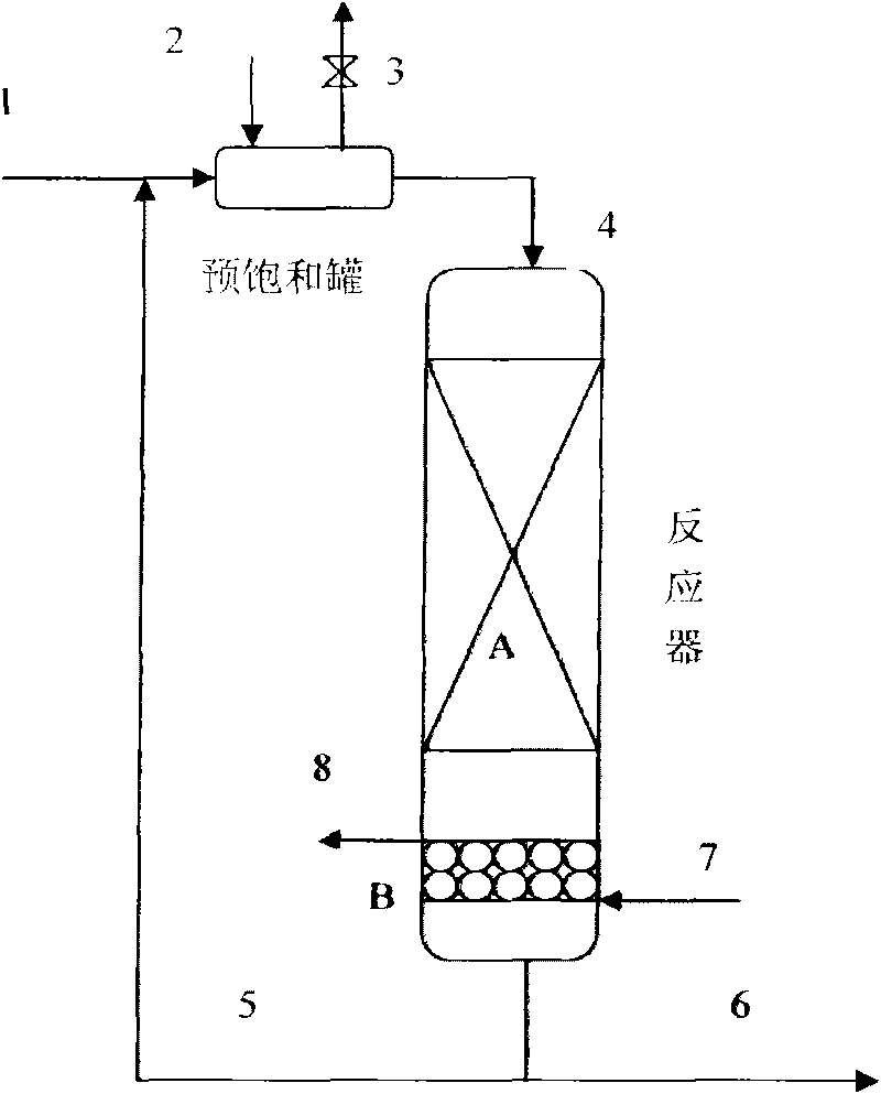
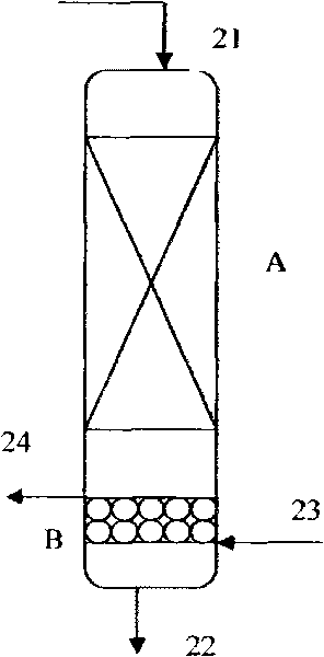
[0031] A single-stage cross-flow reactor is used, the raw materials used are shown in Table 1-1, and the catalyst is FH-UDS hydrorefining catalyst. The composition and quality index of FH-UDS catalyst are shown in Table 1-2, the process conditions are shown in Table 1-3, and the properties of refined diesel oil are shown in Table 1-4.

[0032] Table 1-1. Properties of raw oil

[0033]

[0034] Table 1-2, the composition and quality index of the catalyst

[0035]

[0036] Table 1-3, process conditions

[0037] Process conditions

Example 1

Raw oil

Raw oil 1

reactor

Reverse

[0038] Process conditions

Example 1

Reaction temperature, ℃

340

Reaction pressure, MPa

4.0

Circulation volume ratio

(Circulating oil: fresh raw material)

2

Total volumetric airspeed, h -1

4.0

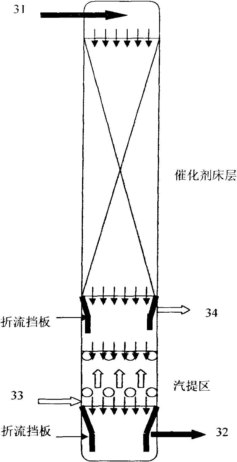
[0039] The process conditions of the cross-flow stripping zone are: nitrogen is used as the stripping gas, the pressure is 4.0 MPa, the temperature is 290°C, and the gas-oil volume ratio is 4...

Embodiment 2

[0043] A two-stage cross-flow reactor is used, the raw materials used are shown in Table 2-1, and the catalyst is FH-UDS hydrofining catalyst. The process conditions are shown in Table 2-2, and the properties of refined diesel oil are shown in Table 2-3.

[0044] Table 2-1. Properties of raw oil

[0045]

[0046] Table 2-2. Process conditions

[0047] Process conditions

Example 2

Raw oil

Raw oil 2

reactor

Two-stage cross-flow reactor

Reaction temperature, ℃

350

Reaction pressure, MPa

6.0

Circulation volume ratio

(Circulating oil: fresh raw material)

1.5

Total volumetric airspeed, h -1

5.0

[0048] The process conditions of the first-stage cross-flow stripping zone are: hydrogen is used as the stripping gas, the pressure is 6.0MPa, the temperature is 350°C, and the hydrogen-to-oil volume ratio is 120:1; the process conditions of the second-stage cross-flow stripping zone are: Using hydrogen as the stripping gas, the pressure is 6.0MPa, the temperature is 2...


PUM


Abstract

The invention discloses a distillate oil two-phase hydroprocessing method, which comprises the following steps of: performing hydrogen saturation on raw materials, hydrogen and circulating hydroprocessing products in a pre-saturation high-pressure tank to form a two liquid-phase mixture of the raw materials, the hydroprocessing products and the hydrogen; separating the hydrogen from the liquid-phase mixture; and putting the mixture with saturated dissolved hydrogen in a single-stage or multi-stage inner cross-flow reactor under the condition of a hydrogenation process. The inner cross-flow reactor adopted by the invention has the functions of catalyzing the hydrogenation reaction and steam stripping the reaction side products such as H2S, NH3 and the like from a reaction system, so the hydrogenation reaction efficiency is greatly enhanced. At the same time, the method does not need a hydrogen circulating link and a circulating hydrogen compressor so as to greatly reduce the equipment investment and the operation cost. The method not only can be applied to hydrogen desulfurization, denitrification and dearomatization for the distillate oil such as gasoline, kerosene, diesel oil and the like, but also can be applied to the technical process for producing high-quality clean fuels by mild hydrocracking the distillate oil such as a VGO raw material.

Description

Technical field [0001] The invention relates to a fixed-bed hydroprocessing method, in particular to a fixed-bed two-phase hydroprocessing method carried out in an internal cross-flow reactor. Background technique [0002] The fixed-bed hydrotreating process is usually a catalytic reaction process to remove impurities such as sulfur, nitrogen, oxygen, and metals in the raw material from crude oil, or to reduce the size of the raw material molecules. In this process, in order to control the reaction temperature of the catalyst bed and avoid the deactivation of catalyst coke deposits, a larger hydrogen-to-oil ratio is usually used. [0003] When a larger hydrogen-to-oil ratio is used for hydroprocessing, there must be a large amount of hydrogen surplus after the hydrogenation reaction is completed. The surplus hydrogen is usually used as hydrogen feed for the reaction after being pressurized by a circulating hydrogen compressor through a hydrogen circulation link and mixed with fres...

Claims


Application Information

Patent Timeline
IPC IPC(8): C10G45/02
Inventor 方向晨宋永一刘继华孙万付李扬
Owner CHINA PETROLEUM & CHEM CORP
Why Eureka
Try Eureka