Al technical title is built by PatSnap Al team. It summarizes the technical point description of the patent document.
A continuous casting roll and process technology, applied in the field of surfacing welding, can solve the problems of poor stress state of the weld bead, time-consuming consumables, and difficult quality assurance, so as to avoid residual shear stress, save money and manpower, and eliminate surfacing welding The effect of blind spots
Inactive Publication Date: 2010-06-16
HARBIN WELDING INST LTD
View PDF0 Cites 4 Cited by
Summary
Abstract
Description
Claims
Application Information
AI Technical Summary
This helps you quickly interpret patents by identifying the three key elements:
Problems solved by technology
Method used
Benefits of technology
Problems solved by technology
[0006] 1. The stress state of the weld bead is not good. The circumferential weld bead formed by the swing has an oblique angle to the axial direction of the continuous casting roll, resulting in shear residual stress, which can easily cause deformation of the small diameter continuous casting roll and difficult installation. The roll breaks during use
[0007] 2. The weld bead cannot completely cover the surface of the continuous casting roll, and a surfacing welding blind zone is formed at both ends of the continuous casting roll
Blind areas need to be surfacing separately, regardless of machine surfacing or manual surfacing blind areas, it will consume time and consumables, and the quality is not easy to guarantee
Method used
Image
Click on the blue label to locate the original text in one second.
Reading with bidirectional positioning of images and text.
[0042] There is no surfacing blind area on the surface of the continuous casting roll, saving time and effort, the surfacing layer is automatically deslagged, no defects, no residual shear stress on the surfacing layer, the continuous casting roll after surfacing has a low fracture probability during use, and is resistant to cold and heat fatigue , high temperature corrosion, strong wear resistance, long service life of continuous casting rolls.
[0053] There is no surfacing blind area on the surface of the continuous casting roll, saving time and effort, the surfacing layer is automatically deslagged, no defects, no residual shear stress on the surfacing layer, the continuous casting roll after surfacing has a low fracture probability during use, and is resistant to cold and heat fatigue , high temperature corrosion, strong wear resistance, long service life of continuous casting rolls.
PUM
Abstract
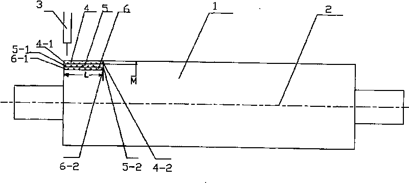
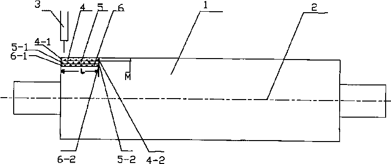
The invention provides a novel continuous casting roller surfacing technology, solving the technical problems of surfacing blind area and poor surfacing stress state which exist in a swing spiral surfacing in the prior art. The novel continuous casting roller surfacing technology mainly comprises the following steps: a continuous casting roller (1) rotates step by step, a weldingtorch (3) moves back and forth for surfacing, that is, the continuous casting roller (1) does not rotate, the weldingtorch (3) moves to (4-2) surfacing from (4-1) surfacing along the direction of an axes (2), the continuous casting roller (1) rotates with a welding bead width M, and the welding torch (3) moves to (5-1) surfacing from (5-2) surfacing along the direction of the axes (2), the continuous casting roller (1) rotates and the welding torch (3) moves in cycles, thereby realizing the surfacing of whole continuous casting roller surface after finishing a cycle of surfacing of the roller surface. The novel continuous casting roller surfacing technology is mainly used for repairing the continuous casting roller (1).
Description
technical field [0001] The invention belongs to the technical field of surfacing welding, and in particular relates to a novel surfacing welding process for continuous casting rolls. Background technique [0002] Continuous casting equipment has been widely used in major steel mills in my country. Continuous casting rolls are the main consumption parts in continuous casting equipment. Continuous casting rolls include three parts: crystallization section, sector section and horizontal section. Especially the crystallization section and fan section, on the one hand, they have to bear the high temperature wear of the high temperature billet and the cyclic load caused by the bulging force and static pressure generated by the billet, and also bear the cold and heat fatigue of the spray cooling water and the high temperature billet. Therefore, after working for a period of time, the roll surface will have wear, corrosion, deformation and thermal fatigue cracks. When the depth of ...
Claims
Application Information
Patent Timeline
Application Date:The date an application was filed.
Publication Date:The date a patent or application was officially published.
First Publication Date:The earliest publication date of a patent with the same application number.
Issue Date:Publication date of the patent grant document.
PCT Entry Date:The Entry date of PCT National Phase.
Estimated Expiry Date:The statutory expiry date of a patent right according to the Patent Law, and it is the longest term of protection that the patent right can achieve without the termination of the patent right due to other reasons(Term extension factor has been taken into account ).
Invalid Date:Actual expiry date is based on effective date or publication date of legal transaction data of invalid patent.
