Method for preparing rocket engine jet pipe and special equipment thereof

A rocket engine and nozzle technology, applied in the direction of machines/engines, casting molding equipment, metal processing equipment, etc., can solve problems such as difficult inner holes, preparation of multi-layer composite coating structures, difficult preparation of high temperature resistance, and erosion resistance. To achieve the effect of improving structure, strong binding force and improving compactness

Inactive Publication Date: 2010-06-16
NO 59 RES INST OF CHINA ORDNANCE IND
View PDF0 Cites 25 Cited by
  • Summary
  • Abstract
  • Description
  • Claims
  • Application Information

AI Technical Summary

Problems solved by technology

[0004] Since the size of the nozzle of the above-mentioned certain high-pressure rocket engine is smaller than that of the conventional nozzle, the throat size is only Φ8mm, and it is a Laval tubular structure, it is difficult for the conventional plasma spraying method to uniform

Method used


Image

  • Method for preparing rocket engine jet pipe and special equipment thereof
  • Method for preparing rocket engine jet pipe and special equipment thereof
  • Method for preparing rocket engine jet pipe and special equipment thereof

Examples


Embodiment 1

[0049] A preparation method of a rocket engine nozzle, which comprises the following steps:

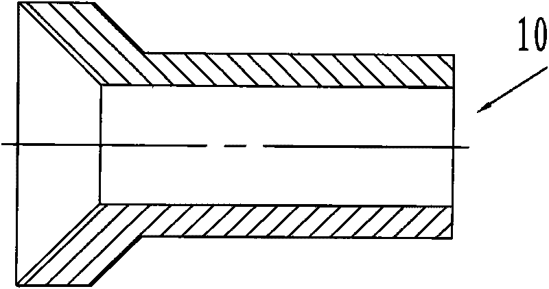
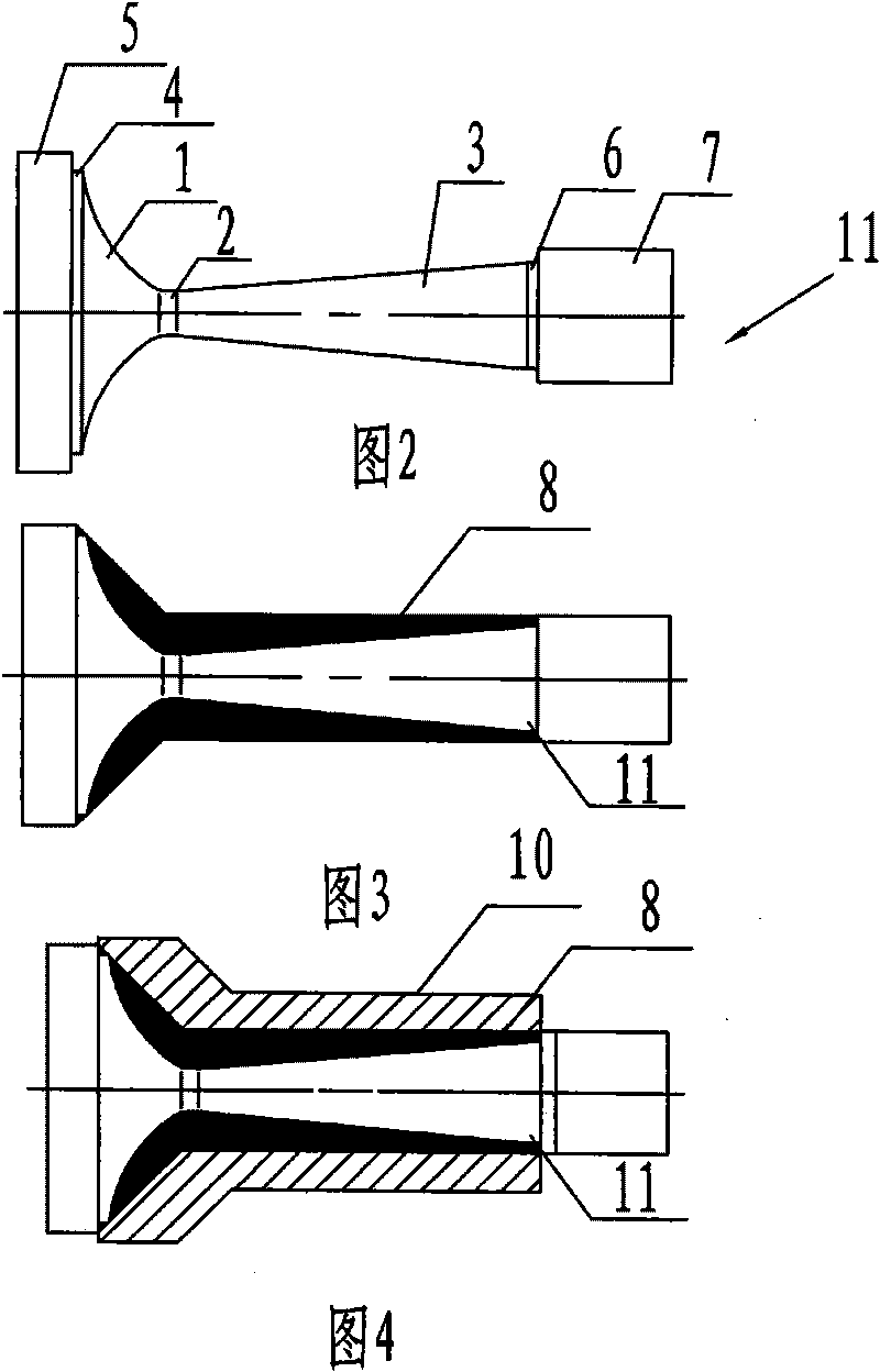
[0050] (1) Using molybdenum as the material to prepare such as figure 1 A blank for a rocket engine nozzle shown; also prepared as figure 2 Graphite mandrels fitted with the inner bore of the prepared nozzle shown;

[0051] (2) Degreasing the graphite mandrel with gasoline and acetone to remove all dirt on the surface of the graphite mandrel, then put the graphite mandrel into an electric furnace and bake at 450°C to 500°C for 1 At the same time, put the tantalum powder, molybdenum powder and zirconia powder for spraying into the oven, bake at 120°C for more than 30min, and then sieve with 120 mesh. Sieve, remove sieve residue;

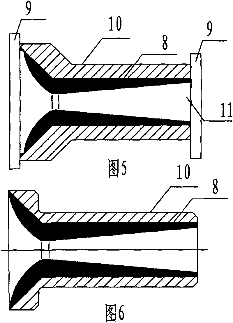
[0052] Then, the surface of the mandrel is sprayed with tantalum powder, zirconia powder and molybdenum powder by the plasma spraying method. The layer in contact with the mandrel is the tantalum powder layer, the middle is the alternating layer of zircon...

Embodiment 2

[0060] A method for preparing a rocket engine nozzle, the specific steps and process parameters of which are the same as those in Embodiment 1, the difference is that high-strength steel is used as a material to prepare a rocket engine nozzle blank.

Embodiment 3

[0062] like figure 2 As shown in the figure, a mandrel is characterized in that: it includes a converging section 1, a throat 2 and an expanding section 3; two cylinders are respectively arranged at both ends of the mandrel, and cylinders are arranged at the end of the converging section 1 in turn A4 and cylinder B5, a cylinder C6 and a cylinder D7 are arranged in sequence at the end of the expansion section 3; the diameter of the cylinder A4 is equal to the maximum diameter of the convergent section 1, and the diameter of the cylinder B5 is greater than the diameter of the convergent section 1 The maximum diameter, the diameter of the cylinder C6 is equal to the maximum diameter of the expansion section 3, the diameter of the cylinder D7 is greater than the maximum diameter of the expansion section 3; the above-mentioned core rod is a graphite core rod.


PUM


Abstract

The invention provides a method for preparing a rocket engine jet pipe, which comprises the following steps: (1) preparing a blank of the rocket engine jet pipe and preparing a core rod of the blank; (2) spraying a coat on the surface of the core rod, grinding the surface of the core rod, and matching the ground core rod with the blank; (3) assembling the ground core rod and the blank on a press, and then sheathing the assembled whole; (5) performing hot isostatic pressing treatment on the sheathed whole in a hot isostatic pressing furnace; and (5) after the hot isostatic pressing treatment, removing the sheathed material and the core rod, and performing fine machining on the jet pipe blank with the coat to obtain the rocket engine jet pipe. The invention also provides special equipment for the preparation method. The method of the invention is not only suitable for the jet pipe with large inner hole size, but also suitable for the jet pipe with small inner hole size and with special requirement for the coat.

Description

technical field [0001] The invention relates to a preparation method of a rocket engine nozzle; the invention also relates to special equipment for the preparation method. Background technique [0002] The pressure of the existing nozzle is about a dozen MPa, and the molybdenum nozzle without coating can fully meet the requirements. The closest preparation method of the nozzle in the prior art is to prepare a metal casing by machining, and then prepare a coating on the inner hole of the metal casing by plasma spraying or chemical vapor deposition; this method can only It is suitable for nozzles with large inner hole size, especially the plasma spraying method is difficult to prepare the multi-layer composite coating structure, and there are also problems such as insufficient dense coating and insufficient bonding force between the coating and the metal shell. [0003] A certain high-pressure rocket engine nozzle needs to be under high pressure (30~50MPa) and high overload (...

Claims


Application Information

Patent Timeline
IPC IPC(8): B23P15/00B22D19/00B22C9/12C23C4/06F02K1/00C23C4/134
Inventor 吴护林张隆平易同斌诸祖渝张津李晓晖
Owner NO 59 RES INST OF CHINA ORDNANCE IND
Why Eureka
Try Eureka