Groove spacing accurately adjusting device in holographic grating manufacturing light path

A precise adjustment and holographic grating technology, applied in the spectrum field, can solve problems such as the inapplicability of the LOY mirror exposure optical system, and achieve the effects of shortening the adjustment time, improving the adjustment accuracy, and simplifying the adjustment steps

Inactive Publication Date: 2010-06-23
CHANGCHUN INST OF OPTICS FINE MECHANICS & PHYSICS CHINESE ACAD OF SCI
View PDF1 Cites 9 Cited by
  • Summary
  • Abstract
  • Description
  • Claims
  • Application Information

AI Technical Summary

Problems solved by technology

However, this setup is for dual-mirror exposure with two adjustment mirrors and is not suitable for LOY mirror exposure optics

Method used


Image

  • Groove spacing accurately adjusting device in holographic grating manufacturing light path
  • Groove spacing accurately adjusting device in holographic grating manufacturing light path
  • Groove spacing accurately adjusting device in holographic grating manufacturing light path

Examples


Embodiment Construction

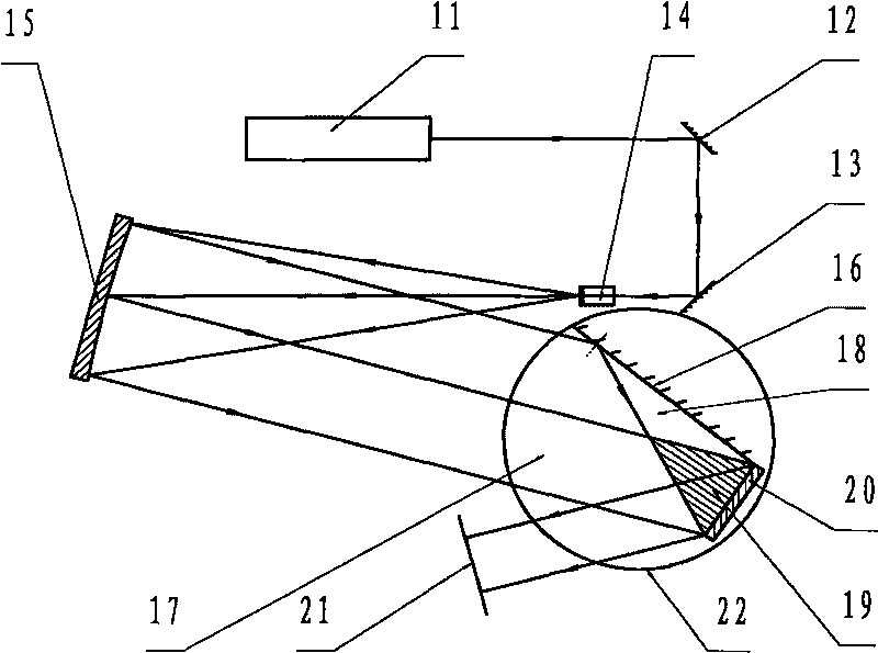
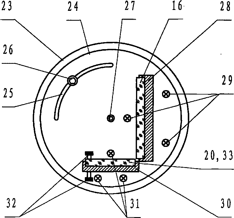
[0012] The invention according to figure 2 , 3 The structure shown in , 4 is implemented, wherein, the laser light source 11 adopts a krypton ion laser, the wavelength is 413.1nm, the first plane reflector 12 and the second plane reflector 13 are aluminum-plated reflectors on glass substrates, and the spatial filter 14 is composed of a display Composed of a micro-objective lens and a pinhole, the diameter of the collimating mirror 15 is φ320mm, the focal length is f=1.2m, the adjusting mirror 16 is an aluminum-plated mirror on a glass substrate, and the reference grating 20 needs to select a reflection grating with a standard reticle density according to actual requirements , the receiving screen 21 is made of ordinary white frosted glass, the grating substrate 33 is made of K9 optical glass, the photoresist coated on the K9 optical glass is Shipley1805 photoresist produced in Japan, and the device for accurately adjusting the line density of the holographic grating All mech...


PUM


Abstract

The invention provides a groove spacing accurately adjusting device in a holographic grating manufacturing light path, and relates to a device belonging to the technical field of light spectrum, aiming to solve the technical problem of providing the device for accurately adjusting the groove spacing in the holographic grating manufactured light path. The technical scheme of the device comprises a laser source, a first plane mirror, a second plane mirror, a spatial filter, a collimating mirror, regulating mirror, an interference field, a reference grating, a receiving screen, a support rotating platform and other parts, wherein pitching and rotation of the adjusting mirror and the reference grating can be changed by regulating an upper turn table on the support rotating platform and adjusting a screw group, so that two recording beams are overlapped to generate moire fringe after being diffracted through the reference grating; through inspection on the moire fringe, accurate regulation on the fringe period of the interference field can be realized, and the spacing of the interference fringe can be taken as the groove spacing for manufacturing the holographic grating. The device simplifies the regulating steps, shortens the regulating time, and improving the regulating precision of the holographic grating groove spacing.

Description

technical field [0001] The invention belongs to the field of spectrum technology and relates to a device for accurately adjusting the density of reticle lines in the light path for making holographic gratings. Background technique [0002] When making a holographic grating, the grating substrate coated with photoresist is exposed in an interference field, and the photoresist records the interference fringes in the interference field, and the density of the interference fringes is the grating line density of the fabricated grating. The line density of the grating determines the dispersion rate and resolution of the grating, and the accuracy of the grating constant directly affects the wavelength accuracy of the spectrometer. Therefore, in the manufacture of holographic gratings, it is very important to precisely adjust the density of reticle lines. [0003] The closest existing technology to the present invention is that the Chinese Patent No. is CN1544994A, and the title of...

Claims


Application Information

Patent Timeline
Patent Type & Authority Applications(China)
IPC IPC(8): G02B5/18G03F7/20G02B7/182
Inventor 李文昊高键翔巴音贺希格齐向东谭鑫曾瑾
Owner CHANGCHUN INST OF OPTICS FINE MECHANICS & PHYSICS CHINESE ACAD OF SCI
Why Eureka
Try Eureka