Software lens

A technology of image acquisition and processing method, which is applied in the field of optoelectronic systems, can solve the problems of affecting imaging details, reducing optical system luminous flux and MTF value, etc., and achieves the effect of weight change, light weight and improved resolution

Inactive Publication Date: 2010-06-23
周春平
View PDF0 Cites 2 Cited by
  • Summary
  • Abstract
  • Description
  • Claims
  • Application Information

AI Technical Summary

Problems solved by technology

In traditional optical systems, in order to expand the depth of field, the usual practice is to reduce the relative apert

Method used


Image

  • Software lens
  • Software lens
  • Software lens

Examples


Embodiment Construction

[0016] The present invention will be further described below in conjunction with the accompanying drawings and embodiments.

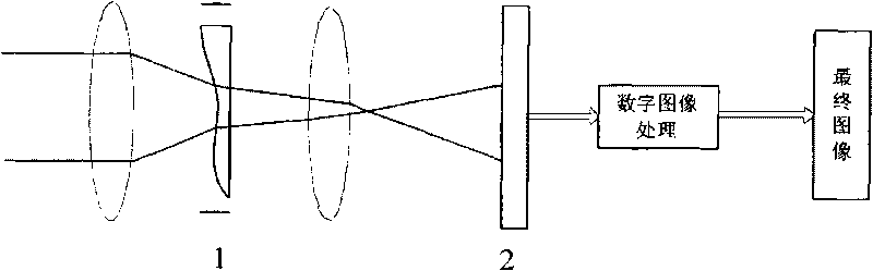
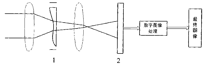
[0017] figure 1 It is a schematic diagram of the software lens system framework. The software lens mainly consists of two parts: the optical system and the digital signal processing system.

[0018] figure 1 Among them, the number 1 is the phase mask, and the number 2 is the CCD. In the traditional optical imaging system, a phase mask is added, which is generally placed on the pupil. When the light path passes through the phase mask, the optical information is captured Encoding, that is, the modulation transfer function (MTF) and point spread function (PSF) of the entire optical system will change. Although the MTF value after encoding is smaller than the value before encoding, it will not appear in the case of defocus Zero value, so it will not cause loss of image detail information.

[0019] What is imaged on the CCD is a fuzzy image, and it is dec...


PUM


Abstract

The invention provides a software lens method which is characterized by comprising the following steps: adding a mask at an optical pupil of an optical system; coding optical information after a light path passes through the mask and imaging a blurred image on a CCD; decoding the optical information by using a digital signal processing system, so that the MTF value of the system is correspondingly improved, thereby recovering a sharp and clear image; imaging two images for frequency domain conversion, extracting high-frequency parts of the two images and aligning and fusing the images. By adopting the software lens method, the system is not sensitive to focal depth, and the resolution ratio of the image can be improved.

Description

technical field [0001] The invention relates to a camera image acquisition and processing method, in particular to a processing method using software technology to achieve a real lens effect, which is suitable for a photoelectric system generating image signals. Background technique [0002] How to expand the depth of field of an incoherent optical imaging system is a hot spot in the field of applied optics research. In traditional optical systems, in order to expand the depth of field, the usual practice is to reduce the relative aperture, but this will reduce the luminous flux and MTF value of the optical system, and ultimately affect the imaging details. Software lens technology can solve these problems very well. [0003] The software lens technology cleverly combines optical technology and digital signal processing technology. By encoding the subject, the modulation transfer function of the optical system is insensitive to discrete quantities, preventing the loss of pa...

Claims


Application Information

Patent Timeline
IPC IPC(8): H04N1/387G02B7/00H04N1/41
Inventor 周春平宫辉力邵洁李小娟吴琼
Owner 周春平
Why Eureka
Try Eureka