
High-power radiating module

A heat dissipation module and metal technology, applied in lighting and heating equipment, cooling/ventilation/heating transformation, cooling/heating devices of lighting devices, etc., can solve problems such as brittle fracture and unfavorable life of electronic parts

Inactive Publication Date: 2010-06-30
MEIKEI TECHONOLOGY CORP
View PDF0 Cites 13 Cited by
  • Summary
  • Abstract
  • Description
  • Claims
  • Application Information

AI Technical Summary

Problems solved by technology

However, every time the electronic parts are switched on and off, the temperature rises and falls rapidly. If the heat cannot be taken away quickly, it will be extremely unfavorable to the life of the electronic parts.
Although soldering is widely used in the industry to weld electronic parts and other metal substrates together, metal tin and other metals, such as copper or aluminum, will react to form intermetallic compounds during soldering. The brittleness of intermediate compounds is very high, and the solder joints often undergo brittle fracture when they are subjected to external stress or thermal stress

Method used

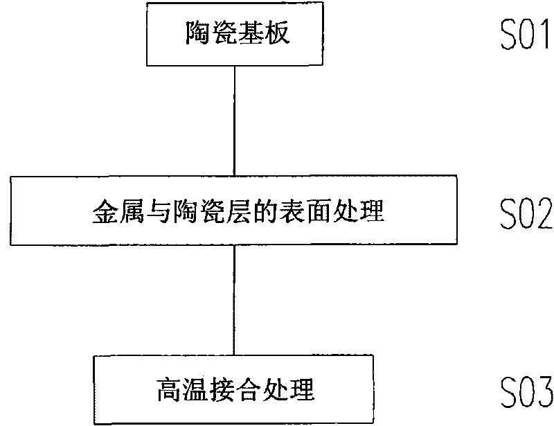
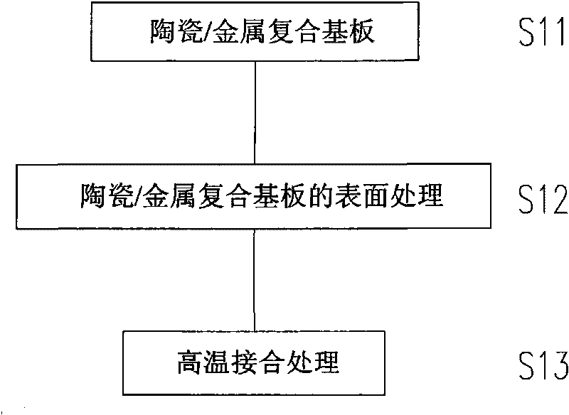

Image

  • High-power radiating module
  • High-power radiating module
  • High-power radiating module

Examples


Embodiment Construction

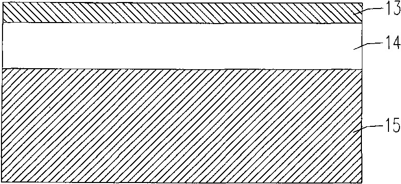
[0035] figure 1 A schematic cross-sectional view of the heat dissipation module according to the first embodiment of the present invention is shown. Such as figure 1 As shown, the heat dissipation module of this embodiment includes: a thin metal upper layer 13 , a ceramic substrate 14 , and a thick metal lower layer 15 .

[0036] In this embodiment, the ceramic substrate 14 is formed of alumina or aluminum nitride, however, the present invention is not limited thereto, and it can be easily understood from the following description that other materials can also be used to form the ceramic substrate 14 .

[0037] The metal upper layer 13 is located above the ceramic substrate 14 . The material of the metal upper layer 13 is selected from the group consisting of gold, silver, copper and alloys thereof. The thickness of the metal upper layer 13 is between 0.1 mm (millimeter) and 1 mm, more preferably between 0.2 mm and 0.6 mm. There may be one or more lines or contacts (not sh...


PUM

PropertyMeasurementUnit
thicknessaaaaaaaaaa
thicknessaaaaaaaaaa
thicknessaaaaaaaaaa

Abstract

The invention relates to a high-power radiating ceramic / metal composite module comprising an upper metal layer, a middle ceramic substrate layer and a large-area lower metal layer. The middle ceramic substrate layer is arranged below the upper metal layer, and the large-area lower metal layer is arranged below the middle ceramic substrate layer; the thickness of upper metal layer is less than 1 / 5 of that of the large-area lower metal layer; and the upper metal layer, the middle ceramic substrate layer and the large-area lower metal layer can be heated at high temperature to be strongly bonded.

Description

technical field [0001] The invention relates to a ceramic / metal composite structure, in particular to a composite structure utilizing a copper sheet, an aluminum oxide substrate, and a copper block. Background technique [0002] When electrons flow in electronic parts, heat will be generated, and the heat generation will increase the resistance, hinder the flow of electrons, and then greatly affect the function of electronic parts. Under the current situation that the manufacturing technology of electronic parts is greatly improved, the line width in electronic parts is getting smaller and smaller, but the circuit density is getting higher and higher, so the heat generated by electronic parts is also increasing rapidly. Taking a computer's central processing unit (Central Processing Unit, CPU) as an example, the earliest version of Intel's Pentium only needs to be packaged with a heat dissipation power of 16W. However, the heat generation of the central processing unit prod...

Claims


Application Information

Patent Timeline
Patent Type & Authority Applications(China)
IPC IPC(8): H05K7/20H01L23/367H01L21/48G06F1/20F21V29/00F21V29/508F21V29/71F21V29/89
Inventor 戚国强林总贤段维新
Owner MEIKEI TECHONOLOGY CORP
Learn More