High-speed wire drawing device for optical fiber production process and high-speed wire drawing method thereof

A medium-to-high-speed production process technology, applied in glass production, glass manufacturing equipment, manufacturing tools, etc., can solve the problems of shortened residence time, insufficient cooling, poor appearance of the coating, etc., to ensure the curing effect and operability Strong, superior performance

Active Publication Date: 2010-07-07
ZHONGTIAN TECH FIBER OPTICS +2
View PDF1 Cites 30 Cited by
  • Summary
  • Abstract
  • Description
  • Claims
  • Application Information

AI Technical Summary

Problems solved by technology

[0003] Due to the limitation of the height of the drawing tower, after the drawing speed is increased, the bare optical fiber coming out of the drawing furnace will be insufficiently cooled due to the shortened residence time at each component, and the coating will be damaged or the appearance of the coating will be poor.
[0004] Chinese patent 200410060906.9 proposes a high-speed wire drawing method, adding a cooling device between the outlet of the inner coating UV curing furnace and the outer coater, and adding a cooling device between the outlet of the outer coating UV curing furnace and the rubbing device, so that The coating resin is fully cured, so as to better protect the optical fiber and prevent the coating from being damaged, but this method is only applicable to the case of a taller drawing tower (the drawing tower should be higher than 25m)

Method used


Image

  • High-speed wire drawing device for optical fiber production process and high-speed wire drawing method thereof
  • High-speed wire drawing device for optical fiber production process and high-speed wire drawing method thereof
  • High-speed wire drawing device for optical fiber production process and high-speed wire drawing method thereof

Examples


Embodiment Construction

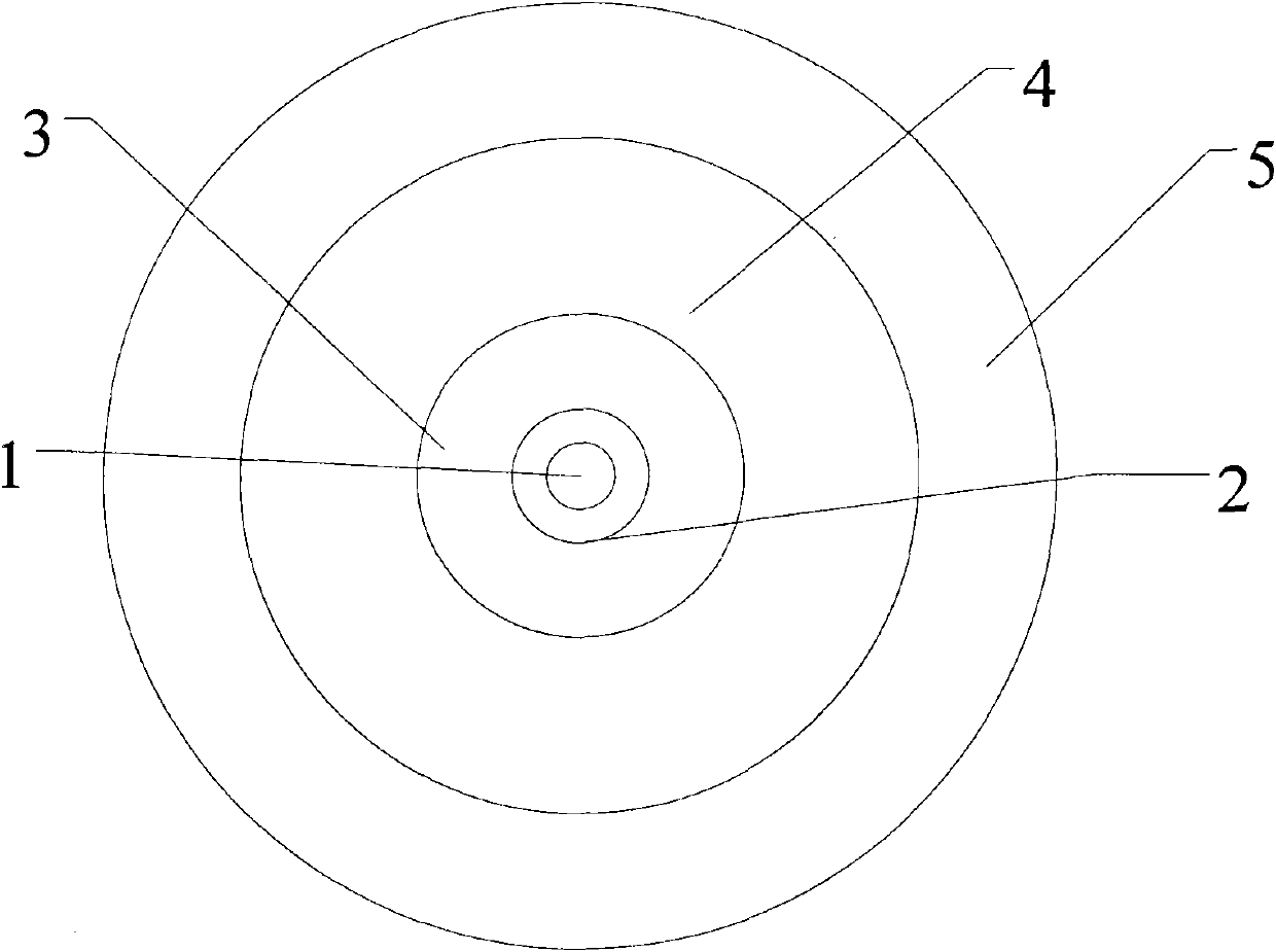
[0027] Refer to attached Figure 1-2 , the single-mode optical fiber produced by the high-speed wire drawing method includes a core 1 , an inner cladding 2 , an outer cladding 3 , a primary UV-curable coating 4 , and a secondary UV-curable coating 5 . The core 1 is wrapped with an inner cladding 2 and an outer cladding 3. There are two layers of UV-curable coatings on the outside of the outer cladding 3, which are the primary UV-curable coating 4 and the secondary UV-curable coating 5. The outer cladding is coated once. , Two-layer coating is formed at one time, and UV-cured coating is used. UV-cured coatings feature low modulus and low refractive index. The index of this optical fiber is basically equivalent to the index of conventional G.652: the zero dispersion wavelength of this optical fiber is between 1300-1324nm, and the zero dispersion slope is not greater than 0.092ps / (nm 2 km). The attenuation of the optical fiber at 1310nm is not greater than 0.34dB / km, and the a...


PUM

PropertyMeasurementUnit
Ash contentaaaaaaaaaa
wavelengthaaaaaaaaaa

Abstract

The invention relates to a high-speed wire drawing device for an optical fiber production process and a high-speed wire drawing method thereof, in particular to a wire drawing method for communication G. 652 optical fiber, particularly relates to a high-speed wire drawing method (with the speed higher than 1500m/min) and a high-speed wire drawing device thereof. The high-speed wire drawing device comprises a rod delivery device, a wire drawing furnace, a cooling pipe, a coating device, a curing device, an air draft device, a rubbing device, a traction wheel and a collecting device, wherein the rod delivery device is arranged on the upper part of the wire drawing furnace, the wire drawing furnace part consists of a graphite heating component and a stainless steel furnace body component, the coating device is arranged at the outlet of the cooling pipe, the curing device is arranged in front of the coating device, and the traction wheel and the collecting device are arranged in front of the rubbing device. The high-speed wire drawing method comprises the following steps: (1) surface pretreatment of a prefabricated rod; and (2) wire drawing: hanging the prefabricated rod after surface pretreatment on the rod delivery device, feeding the prefabricated rod into the wire drawing furnace for wire drawing, adopting ultraviolet light to cure a coating, rubbing an optical fiber through the rubbing device after curing, and after rubbing, collecting the optical fiber through the traction wheel and the collecting device.

Description

technical field [0001] The high-speed wire-drawing equipment and its high-speed wire-drawing method in the optical fiber production process of the present invention relate to a kind of wire-drawing method of G.652 optical fiber for communication, especially relate to the wire-drawing method and its high-speed wire-drawing equipment of higher speed (higher than 1500m / min). And the optical characteristics, geometric parameters, environmental performance and the like of the single-mode optical fiber produced by this method meet the general single-mode optical fiber standard. Background technique [0002] With the rapid development of optical fiber communication in recent years, the requirements for optical fiber are getting higher and higher, and the competition in the industry is becoming increasingly fierce. Improving the drawing speed is an effective way to reduce costs and carry out mass production. In the optical fiber production industry, at present, most domestic manufa...

Claims


Application Information

Patent Timeline
Patent Type & Authority Applications(China)
IPC IPC(8): C03B37/03C03B37/025
CPCY02P40/57
Inventor 薛济萍薛驰沈一春刘志忠薛群山曹珊珊吴椿烽
Owner ZHONGTIAN TECH FIBER OPTICS
Why Eureka
Try Eureka